Rev. A 10/18
20
Application Note AN-72
www.power.com
At the instance of voltage reversal at the winding due to primary
MOSFET turn-ON, the interaction between the leakage reactance of
the output windings and the SR FET capacitance (C
OSS
) leads to
ringing on the voltage waveform. This ringing can be suppressed
using a RC snubber connected across the SR FET. A snubber resistor
of 10 Ω to 47 Ω may be used (higher resistance values will lead to a
noticeable drop in efciency). A capacitance value of 1 nF to 2.2 nF
is adequate for most designs.
When the primary MOSFET turns on, a fast rising voltage is
transfered to the secondary via the transformer across the drain-
source of the SR FET. This high dv/dt combined with high ratio of C
GD
to CISS MOSFET capacitances will induce gate-source voltage on the
SR FET. If the induced gate voltage exceeds the minimum gate
threshold voltage, V
GS(TH)
, then it will turn-on the SR FET causing
cross-conduction possibly leading to catastrophic failure. The
recommended C
GD
(CRSS), is less than 35 pF, and the ratio of CRSS to
CISS to be less than 2%.
Another important parameter in the selection of SR FET is the reverse
recovery time (T
RR
) of its body diode. The reverse recovery
characteristics of the SR FET’s body diode can inuence the level of
voltage stress on the drain when the primary MOSFET switches on.
As shown in Figure 17, the SR FET with a slow body diode (> 40 ns
T
RR
) has twice the voltage stress compared to the one with a fast
body diode. The recommended maximum reverse recovery time
(T
RR
) of the body diode is less than 40 ns.
Output Filter Capacitance (C
OUT
)
The current ripple rating of the output capacitor(s) should be greater
than the calculated value in the spreadsheet, IRIPPLE_CAP_OUTPUT1.
However in designs with high peak to continuous (average) power
and for those with long duration peak load conditions, the capacitor
rating may need to be increased. Selection in this one should be
based on the measured capacitor temperature rise under worst-case
load and ambient temperature conditions. The spread- sheet
calculates the output capacitor ripple current using the average
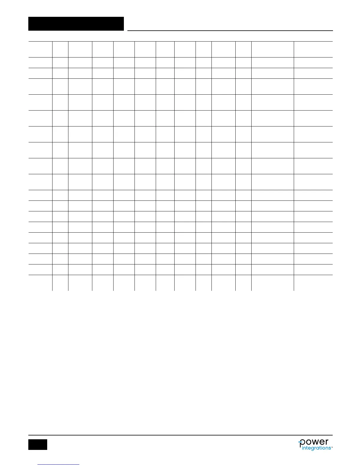
Part PIV I
DRAIN
V
GS(TH)
V
GS(TH)
CISS CRSS
CRSS/
CISS
R
G
R
DS(ON)
T
RR
Package Manufacturer
Max Min
(V) (A) (V) (V) (pF) (pF) (%) (Ω) (Ω) (ns)
AO4260 60 18.0 2.4 1.3 4940 32.0 0.65 0.9 6.3 22
8-SOIC (0.154",
3.90 mm Width)
Alpha & Omega
AO4264 60 12.0 2.5 1.4 2007 12.5 0.62 1.2 13.5 15
8-SOIC (0.154",
3.90 mm Width)
Alpha & Omega
AON6244 60 85.0 2.5 1.5 3838 14.5 0.38 1.0 6.2 17
8-PowerSMD,
Flat Leads
Alpha & Omega
AON6266 60 30.0 2.5 1.5 1340 10.0 0.75 1.5 19.0 17
8-PowerSMD,
Flat Leads
Alpha & Omega
AON7246 60 34.5 2.5 1.5 1340 10.0 0.75 1.5 19.0 15 8-PowerVDFN Alpha & Omega
AO4294 100 11.5 2.4 1.4 2420 11.0 0.45 0.6 15.5 25
8-SOIC (0.154",
3.90 mm Width)
Alpha & Omega
AON7292 100 23.0 2.6 1.6 1170 8.0 0.68 0.7 32.0 24
8-WDFN
Exposed Pad
Alpha & Omega
AO4292 100 8 2.7 1.6 1190 7 0.59 3 33 20 SOIC-8 Alpha & Omega
AO4294 100 11.5 2.4 1.4 2420 11 0.45 3 15.5 25 SOIC-8 Alpha & Omega
AO4296 100 13.5 2.3 1.3 3130 12.5 0.40 3 10.6 28 SOIC-8 Alpha & Omega
AOD294A 100 55 2.5 1.5 2305 11.5 0.50 3 15.5 30 TO-252 Alpha & Omega
AOD296A 100 70 2.3 1.3 3130 12.5 0.40 3 10.6 30 TO-252 Alpha & Omega
AOD2910 100 31 2.7 1.6 1190 7 0.59 3 33 30 TO-252 Alpha & Omega
AOD2916 100 25 2.7 1.6 870 3.5 0.40 3 43.5 20 TO-252 Alpha & Omega
AOD2544 150 23.0 2.7 1.7 675 4.0 0.59 2.9 66.0 37 TO-252 DPAK Alpha & Omega
AON7254 150 17.0 2.7 1.7 675 4.0 0.59 2.9 66.0 37
8-WDFN
Exposed Pad
Alpha & Omega
Table 10. List of MOSFETs Suitable for Synchronous Rectication.