Rev. A 10/18
27
Application NoteAN-72
www.power.com
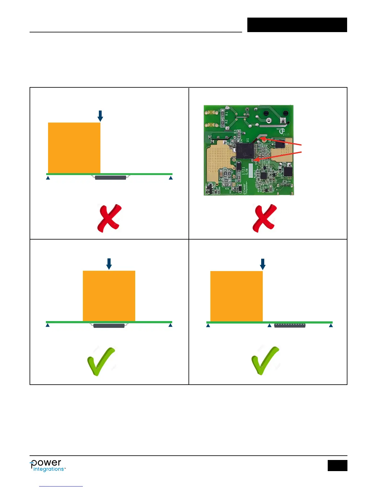
Recommended Position of InSOP-24D Package
with Respect to Transformer
The PCB underneath the transformer and InSOP-24D must be rigid.
If a large size transformer core is used on the board with thin PCB,
(<1.5 mm), it is recommended that the transformer be away from the
InSOP package. Cutting a slot in the PCB that runs near to or
underneath the InSOP package is generally not recommended as this
weakens the PCB. In the case of a long PCB, it is recommended that
mechanical support or post be placed in the middle of the board or
near the InSOP package.
Figure 23. Recommended Position of InSOP-24D Package Shown with Check Mark.
(23-a)
(23-c)
(23-b)
(23-d)
Supporting
Stand-Off
PI-8523-020618
Supporting
Stand-Off
Force
InSOP-24D
Transformer
Supporting
Stand-Off
Supporting
Stand-Off
Force
PI-8524-020618
InSOP-24D
Transformer
Force
Supporting
Stand-Off
Supporting
Stand-Off
InSOP-24D
PI-8525-042618
Transformer
Slot not
recommended