Rev. A 10/18
3
Application NoteAN-72
www.power.com
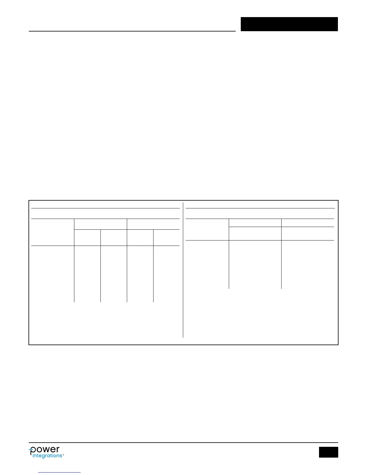
Table 1. Output Power Tables of InnoSwitch3-CE and EP.
• Enter AC input voltage range and line frequency, VAC_MIN [B3],
VAC_MAX [B4], LINEFREQ [B6]
• Enter input capacitance, CAP_INPUT [B7]
• 3 µF / W for universal (85-265 VAC) or single (100/115 VAC) line.
A more aggressive value of 2 µF / W can be used for many
charger designs that do not need to meet hold up time require-
ment
• Use 1 µF/W for 230 VAC or for single (185-265 VAC) line. If this
cell is left blank then the capacitance value for a VMIN of 70 V
(universal input) or 150 V (single 230 VAC) is calculated. Often
this will lead to an optimal input lter capacitance value
• Enter nominal output voltage, VOUT [B8]
• Enter desired cable drop compensation, PERCENT_CDC [B9]
• “0%” for no cable compensation
• “1% - 6%” for featured H-code trim
• Enter continuous output current, IOUT [B10]
• Enter efciency estimate, EFFICIENCY [B12]
• 0.83 for universal input voltage (85-265 VAC) or single 100/115
VAC (85-132 VAC) and 0.85 for a single 230 VAC (185-265 VAC)
design. Adjust the number accordingly after measuring the
efciency of the rst prototype-board at max load and VACMIN
• Select power supply enclosure, ENCLOSURE [B14]
• Select current limit mode, ILIMIT_MODE [B19]
• Two current limit congurations are available, STANDARD or
INCREASED
• Select InnoSwitch3 from drop-down list or enter directly [B20]
• Select the device from Table 1 according to output power, input
voltage and application
• InnoSwitch3-CE for CV/CC yback application
• InnoSwitch3-EP for CV/CC yback application with 725 V
MOSFET
• Enter desired maximum switching frequency at full load, FSWITCH-
ING_MAX [B34]
• Enter desired reected output voltage, VOR [B35]
• Enter core type (if desired), CORE [B63] from drop down menu
• Suggested core size will be selected automatically if none is
entered [B63]
• For custom core, enter CORE CODE [B64], and core parameters
from [B65] to [B72]
• Enter secondary number of turns [B88]
If any warnings are generated, make changes to the design by
following instructions in spreadsheet column D.
• Build transformer as suggested in “Transformer Construction” tab
• Select key components
• Build prototype and iterate design as necessary, entering measured
values into spreadsheet where estimates were used (e.g. efciency,
V
MIN
). Note that the initial efciency estimate is very conservative.
Output Power Table
Product
3
230 VAC ± 15% 85-265 VAC
Peak or
Open Frame
1,2
Peak or
Open Frame
1,2
INN3672C 12 W 10 W
INN3673C 15 W 12 W
INN3674C 25 W 20 W
INN3675C 30 W 25 W
INN3676C 40 W 36 W
INN3677C 45 W 40 W
Notes:
1. Minimum continuous power in a typical non-ventilated enclosed typical size
adapter measured at 40 °C ambient. Max output power is dependent on the
design. With condition that package temperature must be < 125 °C.
2. Minimum peak power capability.
3. Package: InSOP-24D.
Output Power Table
Product
3
230 VAC ± 15% 85-265 VAC
Adapter
1
Open
Frame
2
Adapter
1
Open
Frame
2
INN3162C 10 W 12 W 10 W 10 W
INN3163C 12 W 15 W 12 W 12 W
INN3164C 20 W 25 W 15 W 20 W
INN3165C 25 W 30 W 22 W 25 W
INN3166C 35 W 40 W 27 W 36 W
INN3167C 45 W 50 W 40 W 45 W
INN3168C 55 W 65 W 50 W 55 W
Notes:
1. Minimum continuous power in a typical non-ventilated enclosed typical size
adapter measured at 40 °C ambient. Max output power is dependent on the
design. With condition that package temperature must be < 125 °C.
2. Minimum peak power capability.
3. Package: InSOP-24D.