Rev. A 10/18
30
Application Note AN-72
www.power.com
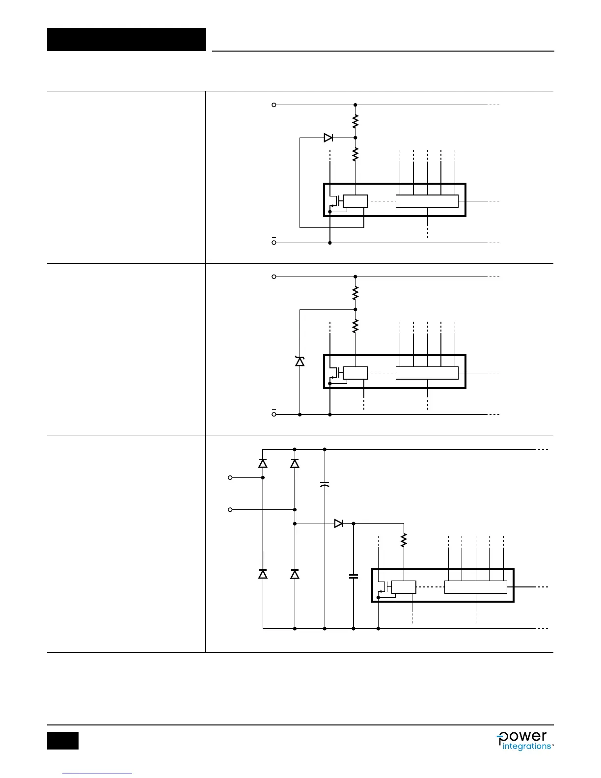
Figure 25. Circuit Ideas to Enhance Design.
Simple Circuit Ideas
Line OV Only
Diode biased from BPP and provides
constant current into the VOLTAGE pin via
R2 above I
UV
threshold, thus disabling UV
function of the IC.
Line UV Only
Zener clamps the voltage on R1-R2 node
and provides constant voltage above I
UV
thresholds, thus disabling OV function of
the IC.
Fast AC Reset for IC with OV Latch
Function
Diode allows VOLTAGE pin to monitor line
voltage for OV/UV detection. A capacitor is
sized to lter the line ripple. C
S
must be
small to allow the VOLTAGE pin to
discharge fast enough to go below the
I
UV-
threshold in order to reset the latch.
PI-8403-081617
D V
R1
R2
1N4148
S IS
VOUT
BPS
FB
GND
SR
BPP
FWD
InnoSwitch3-CE
+
PI-8404-081617
D V
R1
R2
6.2 V
S IS
VOUT
BPS
FB
GND
SR
BPP
FWD
InnoSwitch3-CE
+
PI-8468-100417
D V
R2
C
S
100 nF
Diode
Cap
S IS
VOUT
BPS
FB
GND
SR
BPP
FWD
InnoSwitch3