Rev. A 10/18
34
Application Note AN-72
www.power.com
PI-8374-082018
C4
1000 pF
630 V
C2
10 µF
400 V
C3
10 µF
400 V
C5
22 µF
50 V
C6
4.7 µF
16 V
L1
330 µH
C10
470 pF
250 VAC
C8
330 pF
50 V
C18
560 µF
6.3 V
C12
2.2 µF
25 V
VR2
SMAZ8V2-13-F
8.2 V
C19
680 µF
16 V
C7
2.2 µF
25 V
C14
2.2 µF
25 V
L2
10 µH
L3
10 µH
2
1
FL1
FL2
T1
EE1621
NC
6
5
12 V, 0.7 A
5 V, 0.3 A
RTN
R8
200 kΩ
R22
68 Ω
RT1
10 Ω
R9
47 Ω
1/10 W
D1
DFLR1600-7
600 V
D7
DFLR1200-7
D3
BAV21WS-7-F
VR1
MMSZ5231B-7-F
R26
36 Ω
1/10 W
R6
6.2 kΩ
1/10 W
4
3
D V
S IS
GND
SR
VO
FWD
FB
InnoSwitch3-EP
CONTROL
R24
62 Ω
1/8 W
C22
1 nF
200 V
R25
30 Ω
1/8 W
C21
1 nF
200 V
R12
0.2 Ω
1%
R13
33.2 kΩ
1%
1/16 W
R16
133 kΩ
1%
1/16 W
R30
100 Ω
1/10 W
C24
2.2 nF
50 V
R29
100 Ω
1/10 W
C23
2.2 nF
50 V
Q1
AO6420
Q2
AO4486
R27
1.2 MΩ
1%
1/16 W
BPP
BPS
U1
INN3672C-H602
BR1
DF08S
800 V
F1
1 A
90 - 265
VAC
L N
t
O
R3
2 MΩ
1%
R4
1.8 MΩ
1%
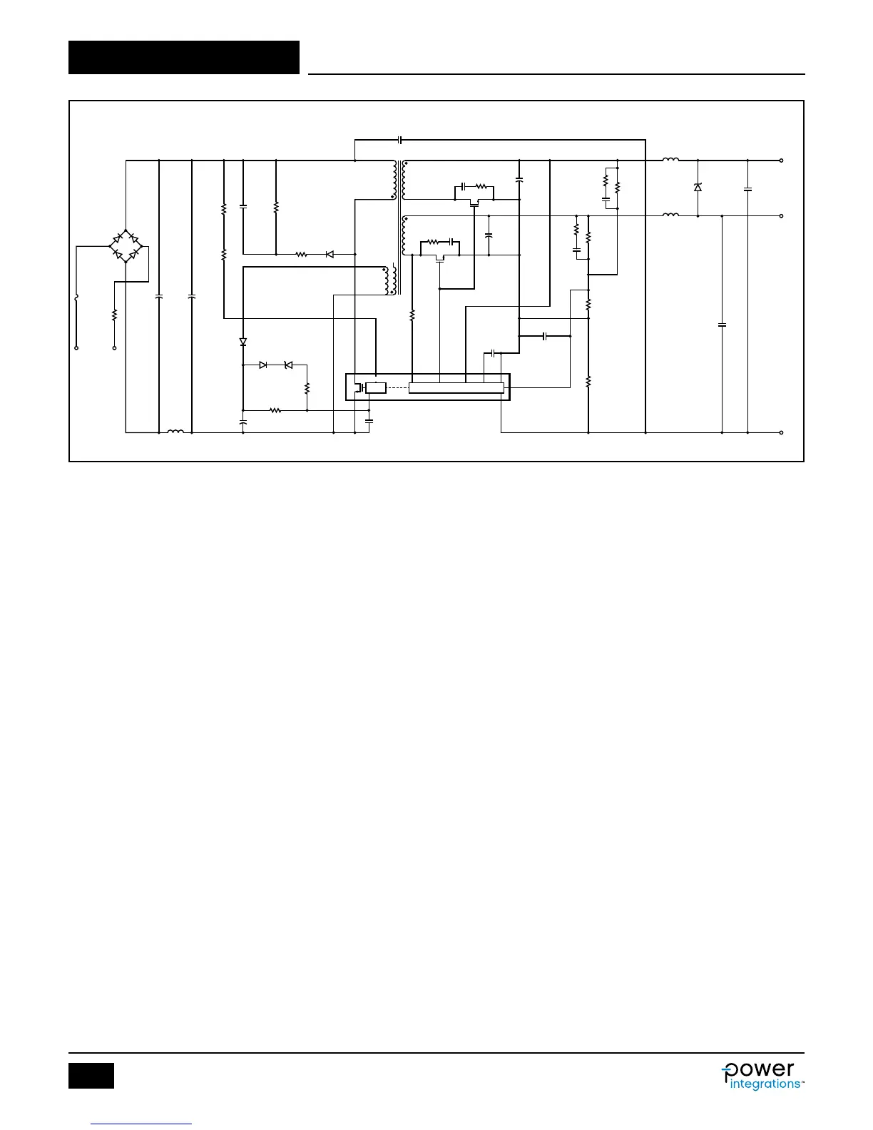
Figure 27. Schematic DER-611, 5 V, 0.3 A and 12 V, 0.7 A for HVAC (Heating, Ventilation and Air-Conditioning) Application.
A High Efciency, 10 W, Dual Output – Universal Input Power
Supply (InnoSwitch3-EP)
The circuit in Figure 27 delivers 10 W output power from 90 VAC to
265 VAC input. Higher than 84% efciency at 90 VAC input at full
load is achieved (using INN3672C from the InnoSwitch3-EP family), and
provides accurate cross regulation between two outputs with two SR
FETs.
Primary-side overvoltage protection is obtained using Zener diode
VR1. In the event of overvoltage occurred on any output, the
increased voltage at the output of the bias winding causes the Zener
diode VR1 to conduct and triggers the OVP latch in the primary-side
controller of the InnoSwitch3-EP IC.
Output rectication of the 5 V output is provided by SR FET Q1, and
output rectication of the 12 V output is provided by SR FET Q2. The
timing of Q1 and Q2 turn-on is controlled by the 5 V winding voltage
sensed via R9 and the FORWARD pin of the IC. Resistor R16, R27
and R13 form a voltage divider network that senses the output
voltage from both outputs to provide better cross-regulation. The
feedback current ratio between 12 V and 5 V outputs is 1:3 to provide
better regulation on the 5 V output and good cross regulation.
Feedback compensation networks comprising capacitors C23 and C24
reduce output ripple voltage. Capacitor C8 provides decoupling to
prevent high frequency noise interfering with power supply operation.
Zener diode VR2 improves the cross regulation when the 5 V output
only is fully loaded when no-load is present on the 12 V output.