38
WARRANTY
CENTER
C
E
R
T
I
F
I
E
D
SECTION 2.5 – Hydraulic Systems
Pump Valve Replacement (Continued)
CM1 & CM2 Pumps
REPLACE PUMP VALVES (Continued):
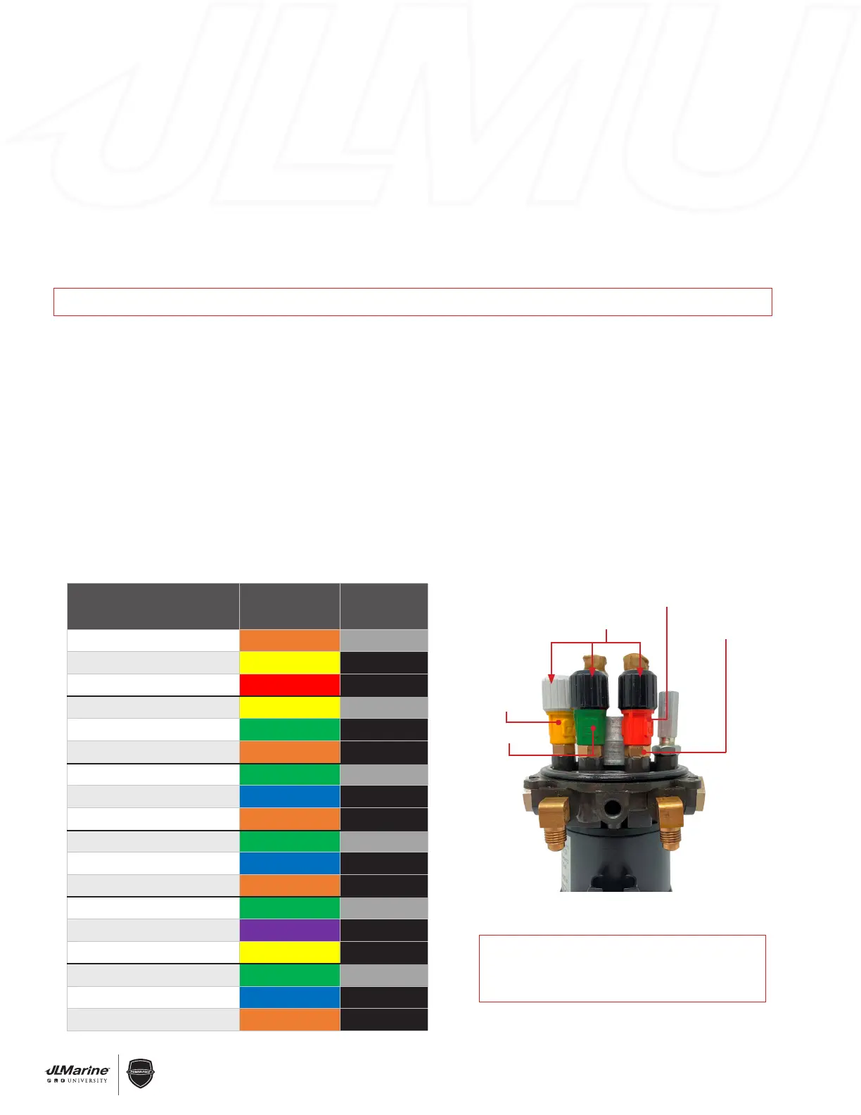
STEP 8 Find your Power-Pole Model in the chart below to determine valve configuration.
STEP 9 Insert new Pump Valves and hand tighten. Once hand-tightened, tighten Hex Nuts a quarter turn with a
9/16” Wrench. DO NOT OVER-TIGHTEN. FIG. 6
IMPORTANT! If properly installed, all valves will be level. Ensure the Valve Housing was removed as shown in FIG 4.
REASSEMBLE PUMP:
STEP 1 Place HPU Back on Reservoir and line up bolt holes. Reinstall the four bolts that hold HPU to Reservoir.
STEP 2 Reattach UP & DOWN Hoses.
CM2: Hand tighten fittings and then tighten 1/4 turn with a 5/8” wrench.
CM1: Insert Tubing into Fittings, thread Nut onto Fittings, then tighten Nuts by holding the Fitting Bases with
a 1/2” Wrench and turning Nut with a 9/16” Wrench.
IMPORTANT: Nuts must be tightened down so that none of the Compression Fitting Threads are visible.
STEP 3 Follow STEP 2 of REPLACE PUMP VALVES section in reverse order to re-install pump.
STEP 4 Reconnect Power to pump.
STEP 5: Follow PRIMING INSTRUCTIONS Section 2.6.
Valve Caps
Down TRV
Down PRV
UP PRV
Hex Nuts
(9/16” Wrench)
Figure 6
BLD 8’ Example
POWER-POLE MODEL VALVE COLOR
VALVE CAP
COLOR
Blade 10’ TRV Down
ORANGE Gray
Blade 10’ PRV Down
YELLOW Black
Blade 10’ PRV Up
RED Black
Blade 8’ TRV Down
YELLOW Gray
Blade 8’ PRV Down
GREEN Black
Blade 8’ PRV Up
ORANGE Black
Pro II 8’ TRV Down
GREEN Gray
Pro II 8’ PRV Down
BLUE Black
Pro II 8’ PRV Up
ORANGE Black
Pro II 6’ TRV Down
GREEN Gray
Pro II 6’ PRV Down
BLUE Black
Pro II 6’ PRV Up
ORANGE Black
Pro II 4’ TRV Down
GREEN Gray
Pro II 4’ PRV Down
PURPLE Black
Pro II 4’ PRV Up
YELLOW Black
Spn II 8’ TRV Down
GREEN Gray
Spn II 8’ PRV Down
BLUE Black
Spn II 8’ PRV Up
ORANGE Black
IMPORTANT:
MAKE SURE ENTIRE DOWN TRV ASSEMBLY
WAS REMOVED AND ALL VALVES ARE LEVEL!
 Loading...