www.powerprobe.com • 800-655-3585
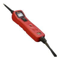
Power Probe Basic
9
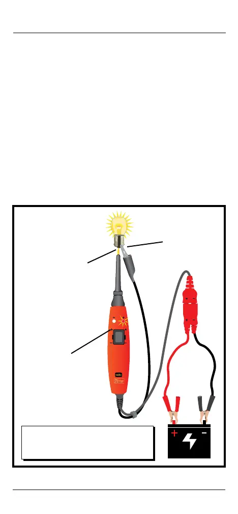
ACTIVATING REMOVED COMPONENTS
By using the Power Probe tip together with the auxiliary ground lead,
components can be activated, thereby testing their function.
Connect the negative auxiliary clip to the negative terminal of the
component being tested.
Contact the probe to the positive terminal of the component, the
LED indicator should light GREEN indicating continuity through the
component.
While keeping an eye on the green LED indicator, quickly depress and
release the power switch forward (+). If the green indicator changed
instantly from GREEN to RED you may proceed with further activation.
If the green indicator went off at that instant or if the circuit breaker
tripped, the Power Probe has been overloaded. This could happen for
the following reasons:
• The contact is a direct ground or negative voltage.
• The component is short-circuited.
• The component is a high amperage component (i.e., starter motor).
If the circuit breaker is tripped, it’ll automatically reset to default
position.
6 -12 VOLTS
Connect the
negative auxiliary
clip to bulb casing
Contact the tip
to the positive
terminal of the bulb
Press the power switch
forward to activate
the bulb
Other than light bulbs, you can also activate
other components like fuel pumps, window
motors, starter solenoids, cooling fans,
blowers, motors, etc.