Document Operating and Maintenance manual, AC200
Reference No. 164571
Revision A
Date 23-JUL-2021
Author AK
Power Prove www.powerprove.com
Leicester. LE5 5LZ. United Kingdom sales@powerprove.com
a division of Cressall Resistors Ltd. +44(0) 116 249 1722 Page 5 of 12
Typical temperatures of the load bank:
• Resistor elements ~500degC above ambient (light/red glow)
• Air outlet surfaces ~250degC above ambient
• Exhaust air ~100degC above ambient at 1m from the outlet
FIRE AN D B URNS H A ZARD ! Failure to maintain proper housekeeping and properly securing flammable material
could lead to fire, burns, and/or injury. Instructions for safe ventilation of the load
bank:
1) Position the load bank on a flat surface that is free from surface finishes or contamination that are flammable.
2) Provide 2m clearance around the load bank inlet and sides, and 4m from the air outlet.
3) Never block or obstruct the air inlets or outlets in any way.
4) Clear any combustible material out of the test vicinity including light materials that could be drawn into the inlet
by the force of the fan suction.
5) Material can be moved by the force of the fan airflow and both the air intake and exhaust. Failure to secure
material could cause injury to bystanders, damage to the load bank or other nearby equipment.
6) Do not let bare skin touch hot surfaces to avoid burns.
7) Do not insert or allow foreign objects to enter any ventilation or exhaust opening as this may cause an electric
shock, fire, or damage the heater/load bank.
8) Always permit the load bank to run its cooling cycle at the end of a load run, this allows the resistor elements
and supporting insulation materials to cool properly. Failure to do so may shorten the resistor element service
life.
9) Ductwork must not be attached to either the air intake or exhaust of this load bank. This will cause a
backpressure that may be harmful to the resistors.
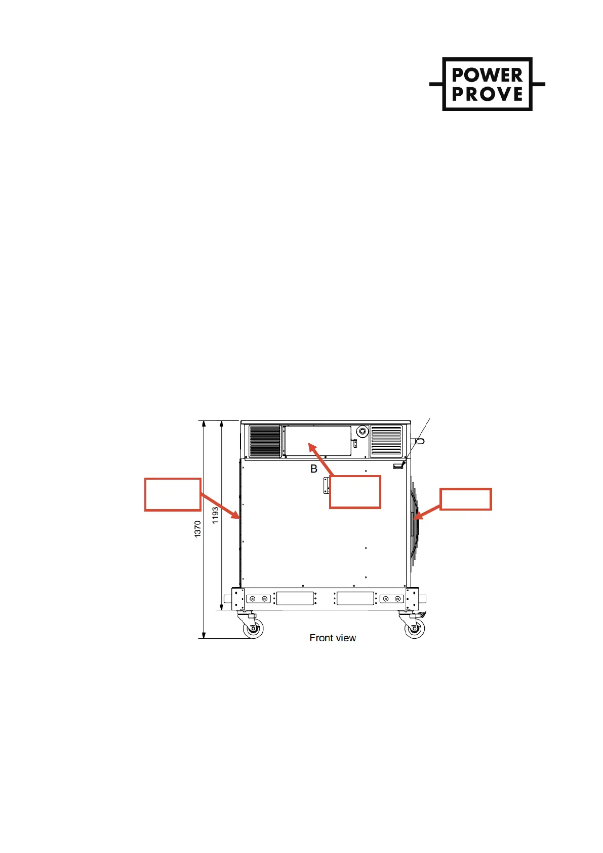
Figure 2 - Unit front view showing ventilation areas
 Loading...