Document Operating and Maintenance manual, AC200
Reference No. 164571
Revision A
Date 23-JUL-2021
Author AK
Power Prove www.powerprove.com
Leicester. LE5 5LZ. United Kingdom sales@powerprove.com
a division of Cressall Resistors Ltd. +44(0) 116 249 1722 Page 6 of 12
4) Operating Instructions
IMPORT AN T ! Read section 3, safety instructions before continuing.
Connections
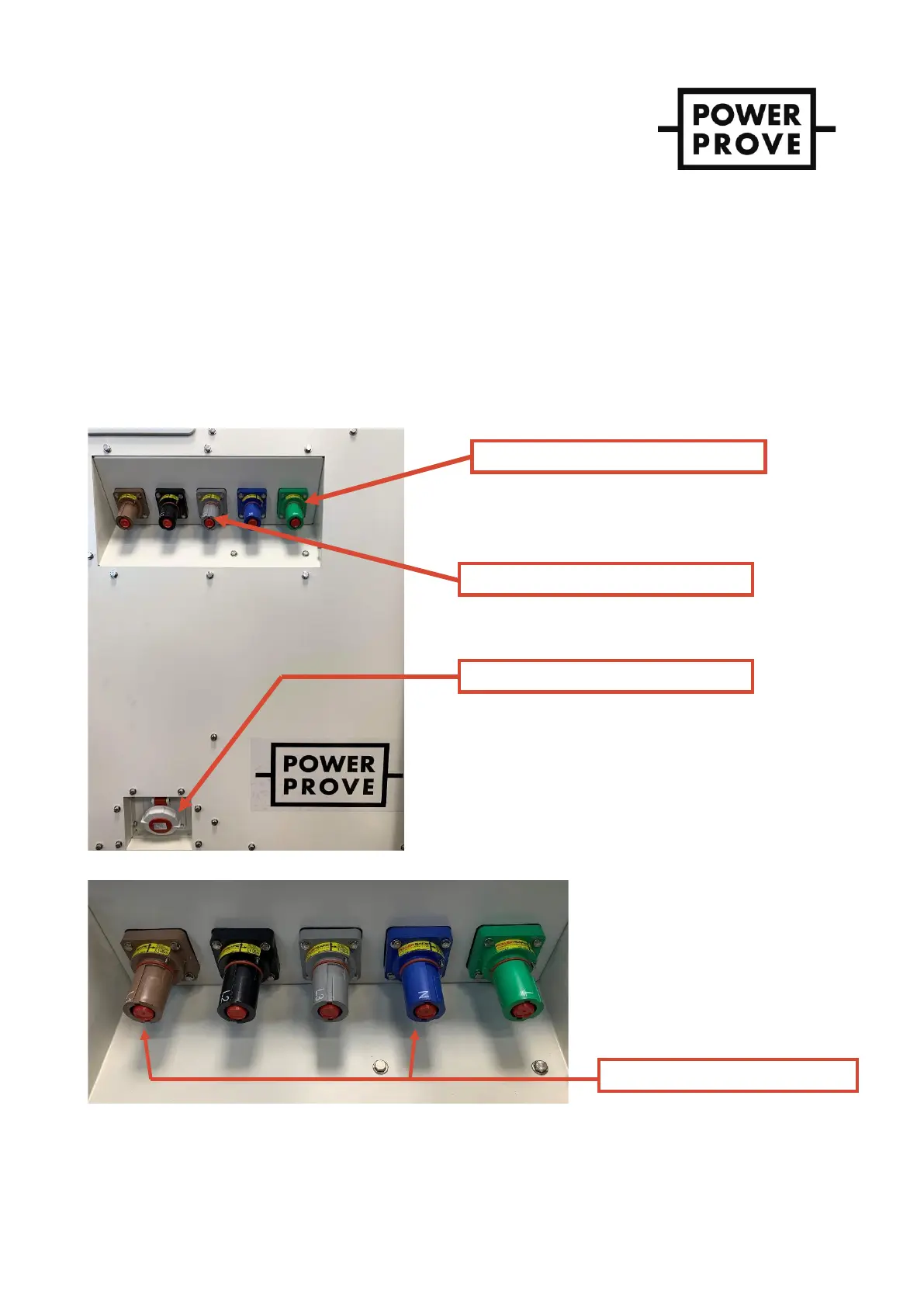
Ensure the protective earth connection is made first, then connect the external control supply if (as recommended) you are
using this, and finally the load power connections (See Figure 3). Otherwise ensure the unit’s Control Source switch is
properly set and the voltage input to the Powersafe sockets is appropriate to supply the units control circuits as well as
the full load.
Connection sockets to be used for 1-phase operation are shown in Figure 4Error! Reference source not found..
Figure 3 - Powersafe load connections, control power (C14 socket) and Protective Earth stud
Figure 4 - Load power connections showing 1-phase configuration.