Document Operating and Maintenance manual, AC200
Reference No. 164571
Revision A
Date 23-JUL-2021
Author AK
Power Prove www.powerprove.com
Leicester. LE5 5LZ. United Kingdom sales@powerprove.com
a division of Cressall Resistors Ltd. +44(0) 116 249 1722 Page 7 of 12
Controls
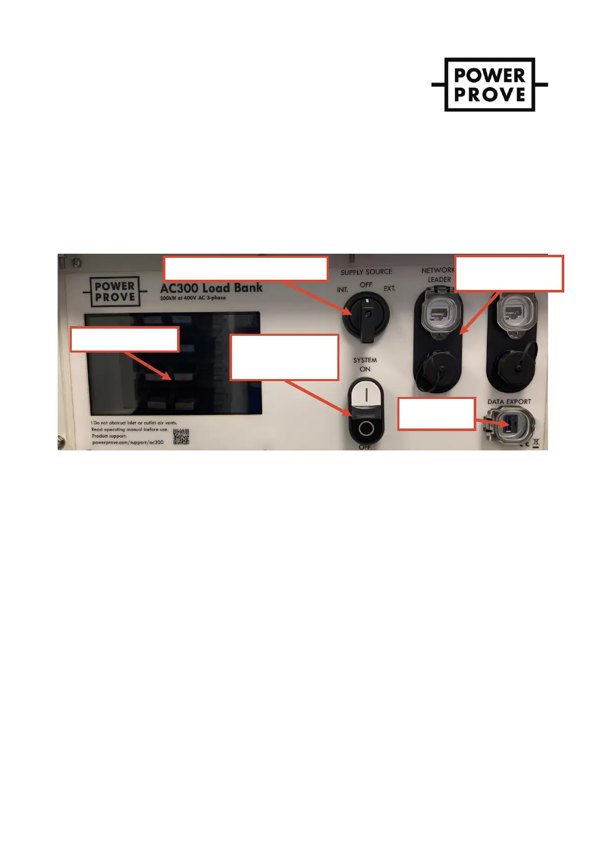
The load bank is controlled from the panel fitted to the load bank behind the padlock-able access door – see Figure 5.
IMPORT AN T ! The unit is also fitted with an emergency stop button, located outside of the area covered by
the control access door to always be accessible. The emergency stop cuts power to the load
contactors and the load cooling fans. Using the emergency stop will mean the latent heat of
each resistor element is retained and the load bank will take a significant period to cool
down. Therefore, use of the emergency stop should be reserved for its intended purpose and
the controlled shut-down process described later should be used for all other occasions.
Figure 5 – User control panel.
Pre-start-up
1. Check housekeeping in the area in which the load bank is operating and rectify anything that is unsafe or
does not comply with the safety instructions in section 3. Failure to do this presents a significant fire hazard.
2. Connect the load bank’s protective earth connection to a known external earth point.
3. Ensure all power supply and load connections are well made, no conductors are exposed, cable sizes used
are appropriate and suitably positioned for the conditions.
Start-up
1. The control circuitry including the load and cabinet cooling fans can either be supplied directly
from the main load connections or from a separate supply using the provided 16A 3-phase socket.
The latter is preferred because should the supply under test cut off the cooling fans will be
supplied ensuring the load bank is not left without cooling. Select the supply source using the
selector switch.
i. “INT.” or internal uses the main supply connected to the load Powersafe sockets.
ii. “EXT.” or external uses supply from the 16A commando socket.
The white LED in the system on/off cluster should now be illuminated indicating the control
circuitry has power.
The cabinet conditioning circuit (ventilation fans and anti-condensation heater) now has power
and will begin to operate.
 Loading...