Document Operating and Maintenance manual, AC200
Reference No. 164571
Revision A
Date 23-JUL-2021
Author AK
Power Prove www.powerprove.com
Leicester. LE5 5LZ. United Kingdom sales@powerprove.com
a division of Cressall Resistors Ltd. +44(0) 116 249 1722 Page 8 of 12
2. Switch on the system using the white ON button marked “I”. The internal control system computer
will now begin its start-up boot sequence, this will take around 2 minutes. When the boot sequence
is complete you will see the Human Machine Interface (HMI) displayed on the touchscreen monitor.
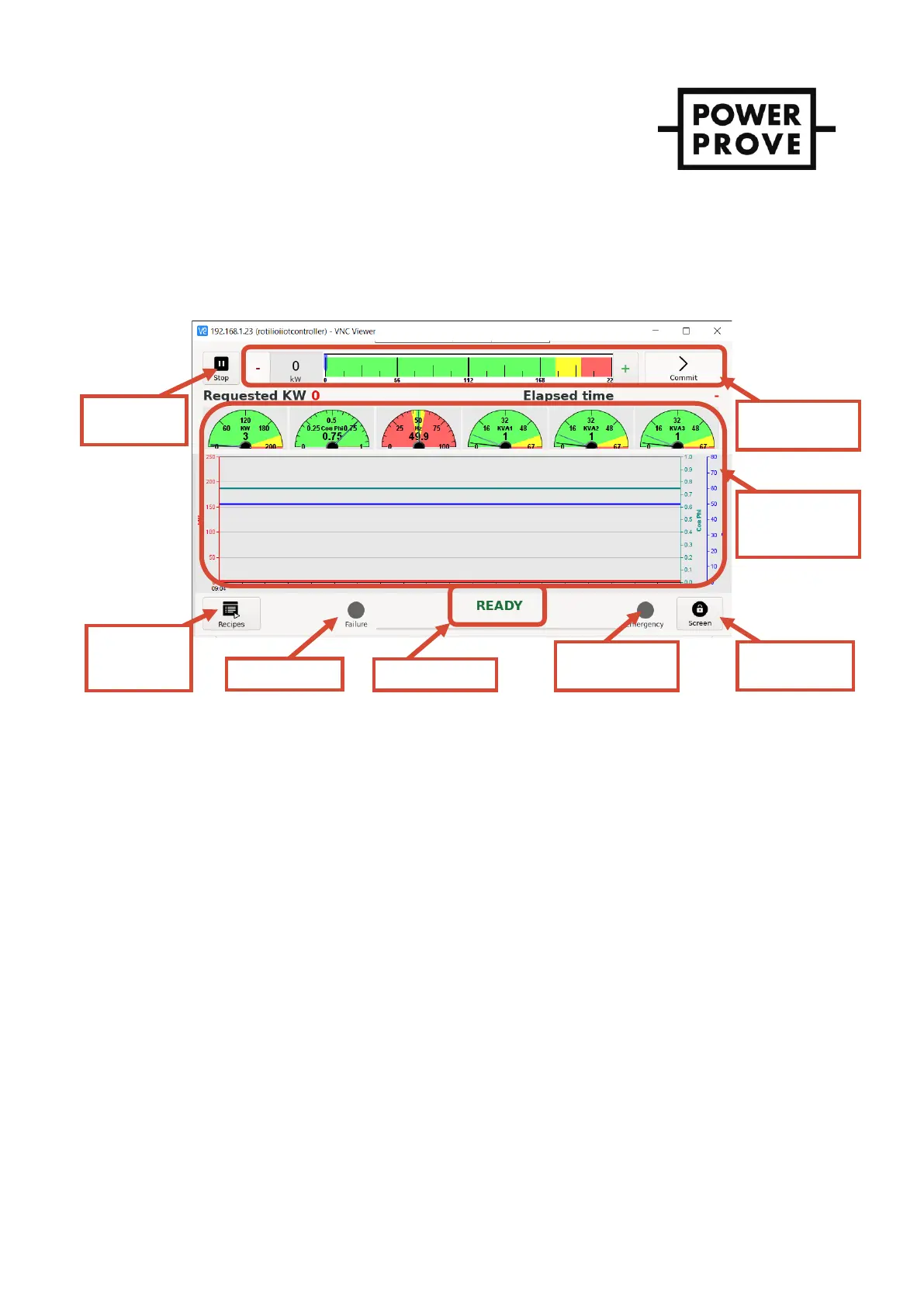
3. The system status will be displayed as “IDLE” – see Figure 6.
DIGILOAD HMI
Figure 6 - DIGILOAD HMI interface
Applying & disconnecting load
1. Before any load can be applied the fan must be running. With the control system status displayed as IDLE,
start the fan using the Start/Stop button in the top left corner for the HMI.
2. When the fan has started the system status will change from “IDLE” to “READY”. Check that the airflow is in
the right direction, into the fan and out of the resistor bank grill.
3. To apply load press and hold the “+” or “-“ buttons until the desired load is shown in the load selection
window and then press “Commit” to confirm the selection. The appropriate contactors will immediately
operate, and the load is applied.
4. The power measurement window will display the measured values confirming the load applied to the
device under test.
5. Further adjustments to the load can be made by repeating the process described in point 3.
6. When the testing is complete simply press the “Start/Stop” button which will change state to show
“Confirm”. Press again to confirm and the load bank status will change to “COOLING DOWN”. This
sequence ramps down the load and then continues to run the fan for the required cooling time. The cool
down progress bar is displayed below the system status.
7. Once complete the system status will return to IDLE and the load bank can be switched off by pressing and
holding the black off button marked “O” for 5 seconds. The internal PSU contactor will de-energise and the
HMI screen will switch off.