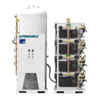
Scroll Medical & Laboratory Compressed Air Systems
Powerex • 150 Producon Drive • Harrison, OH 45030 • USA
P 1.888.769.7979 • F 513.367.3125 • www.powerexinc.com
IN907800AV • 08/2018
Page 4 of 40
Wiring
Lock out and tag out the electrical supply before
servicing the equipment.
requirements.
Electrical shock hazard. Make sure the system
is grounded in accordance with NEC and local
All electrical hook-ups must be performed by a qualied electrician.
Installaons must be in accordance with local and naonal electric
codes. Make sure power supply conductors are sized adequately for
full system demand.
Use solder-less terminals to connect the electrical power source.
Piping
General Guidelines
Refer to the general product manual.
1. Make sure the piping is lined up without being strained or
twisted when assembling the piping for the system.
2. Appropriate expansion loops or bends should be installed at
the system to avoid stresses caused by changes in hot and cold
condions.
3. Piping supports should be anchored separately from the
system to reduce noise and vibraon.
4. Never use any piping smaller than the system outlet connecon.
5. Use exible hose to connect the outlet of the system to the
piping so that the vibraon of the system does not transfer to
the piping.
water going into the pumps will damage the pumps and void the warranty.
The intake lters supplied by Powerex will not
stop ingeson of liquid water by the pumps. Liquid
Remote Intake Piping
Use a exible connector to join the facility piping to the system
single point intake.
Size the remote intake piping to minimize pressure loss due to ow
fricon. Use the following guidelines to determine the minimum pipe
size. Larger size piping will reduce losses.
A compressor system intake must be located to comply with
applicable regulaons and should be arranged to provide the cleanest
air possible for compression. Follow all requirements of NFPA 99 for
locaon and materials.
In addion, the inlet system must be designed to avoid pressure
drop or creang a signicant vacuum on the intake side of the pumps
and to avoid any condensaon formed by cooling of humid intake
air from reaching the pumps. A drip leg, or mulple drip legs may
be necessary. Drain the drip legs frequently to prevent water from
reaching the pumps. Water will damage the pump and void the
warranty.
To determine the minimum required pipe size for a compressor
system intake, calculate the equivalent straight length of the run.
Installaon
Frames or Tank Mount Structure
Powerex designed the system to bear the weight and stress of
the compressor pumps, controls, and receiver tank. When liing
the system, use the designated fork li slots or rig straps to li the
main system skid. Do not aempt to li the system using individual
component liing hooks and eyes. Piping may need to be supported
to avoid damaging the supplied ex connectors for intake and exhaust.
Operaon at High Altudes
Compressor pumps are sensive to reduced atmospheric pressure
encountered as altude increases. Powerex will adjust the operang
set points to compensate for altude if the original order is designated
for high altude and the expected condions provided to us.
Disconnect, tag and lockout power before
aempng to install, service, relocate or perform
any maintenance.
Do not li or move unit without appropriately rated
equipment. Be sure the unit is securely aached to
liing device used. Do not li unit by holding onto tubes or coolers. Do not
use pumps to li other aached equipment.
Installaon Site
1. The compressor system must be located in a clean, well lit and
well-venlated area.
2. The area should be free of excessive dust, toxic or ammable
gases and moisture.
3. Never install the system where the surrounding temperature is
higher than 104°F or where humidity is high.
4. Clearance must allow for safe, eecve inspecon and
maintenance.
MINIMUM CLEARANCES
Above 24 inches
Other sides 24 inches
Control Panel side 36 inches
5. If necessary, use metal shims or leveling pads to level the
system. Never use wood to shim the unit.
Venlaon
1. If the oil-less compressor system is located in a totally enclosed
room, an exhaust fan with access to outside air make up air
must be installed. Room temperature must remain below
104°F. Circulaon must be sucient to prevent local hot spots.
2. Never restrict the cooling fan exhaust air. Maintain a minimum
of 24 in. of clearance around the enre unit (36 in. is preferred).
3. Never locate the compressor where hot exhaust air from other
heat generang units may be pulled into the system.
 Loading...