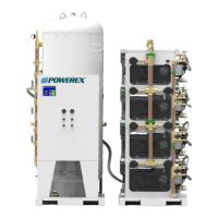
Scroll Medical & Laboratory Compressed Air Systems
Powerex • 150 Producon Drive • Harrison, OH 45030 • USA
P 1.888.769.7979 • F 513.367.3125 • www.powerexinc.com
IN907800AV • 08/2018
Page 6 of 40
4. Follow steps 1 to 3 for ex line from dryer package to inlet of
receiver tank (if applicable).
NOTE: All piping is provided and sealed for this poron of
installaon.
5. If applicable, locate and aach intake inline air lter to outside
source air or header. A ex line is provided for aaching intake
of compressors to air lter assemblies.
6. Connect outlet of tank/dryer module to outlet source piping.
Electrical Wiring of System Shipped In Separate Modules
Provide electrical power in accordance to NEC
and local codes. Connecon of wiring should be
performed by a qualied electrician.
1. Systems are provided with overload protecon. A main system
service disconnect must be installed. Powerex recommends
the main system disconnect should be placed as close as
possible to the system.
2. Refer to the system wiring diagram. Temperature switches
shutdown the compressor when temperature reaches above a
pre-set limit. Connect dryer power cords, electric drain power
cord, dew point power cord, and alarm wiring to the master
control panel.
3. The system has a terminal strip in the control panel with
“landing points” for the master alarm panel connecons.
Locate the supplied landing points and install wire connecons
as appropriate.
4. Wiring connecons can become loose during shipping and
storage. Check all connecons for integrity when installing and
starng unit.
For quesons concerning assembling and start-up, contact Powerex
at 1-888-769-7979 for technical assistance.
Operaon
Before Start Up
1. Make sure all safety warnings, labels and instrucons have
been read and understood before connuing.
2. Remove any shipping materials, brackets, etc.
3. Conrm that the electric power source and ground have been
rmly connected. Conrm supply voltage and amps match the
system requirements.
4. Be sure all pressure connecons are ght.
5. Check to be certain all safety relief valves, etc. are unrestricted.
6. Check that all fuses, circuit breakers, etc. are the proper size.
7. Make sure the inlet lter assembly is properly installed and all
intake isolaon valves are open.
8. Conrm that the tank manual drain valve is closed.
9. Once power is connected to the unit, visually check the
rotaon of the compressor pump. If the rotaon is incorrect,
have a qualied electrician correct the motor wiring.
Safety Valves, Pressure Vessels, and Piping
1. Powerex systems are shipped with ASME safety valves sized so
that the maximum system ow is less than the capacity of the
valve or valves at the rated pressure. The rated pressure of the
valve is equal to or less than the maximum allowable working
pressure of the vessel or upstream pressure bearing parts. DO
NOT MODIFY or install any valves with dierent specicaons
unless appropriate evaluaons are completed. Do not modify
the structure of the pressure vessel or weld on the vessel.
2. Do not install any shut o valves between the safety valve
and the vessel or between the compressor pump and the
rst system safety valve. Doing so can result in a dangerous
condion and lead to death or injury.
3. Do not install shut o valves in the system that create trapped
compressed air.
4. Manually operate the safety valve every six months or 2,500
operang hours to provide assurance that the mechanism is
free to operate. Replace valve if it is leaking when it is closed
or if it fails to vent when actuated.
5. Any piping or pressure bearing connecon hose or tubing used
in the system must be rated equal to or higher than the safety
valve pressure rang. Inadequate pressure rang could result
in bursng.
Modular Placement
1. Unpack each frame module and discard or recycle all wood
shipping materials.
2. Systems consist of mulple frame modules. The steel base
plaorms are intended to be bolted to the oor as shown in
the design drawings and connecng hoses provided (found in
the parts pack box). Systems may be placed on isolaon pads
if desired. Modules may be spaced farther apart without any
structural problems, but electrical connecons may need to be
modied—addional isolaon pads and longer hoses may be
needed.
3. Place frame modules at locaon designated on build drawing.
Provide sucient clearance around system for servicing (see
minimum clearance secon).
4. Install frame assembly fasteners to each frame joining the
frames together.
5. Li corners of each frame assembly and install isolaon pads
provided.
Connecng Piping (if applicable)
1. Locate connecon for piping at rear of compressor module to
receiver tank module.
2. Remove plasc caps or adhesive covering on ports and
connectors.
3. Connect ex line to the ports making sure each ex line is not
pinched or kinked.
 Loading...