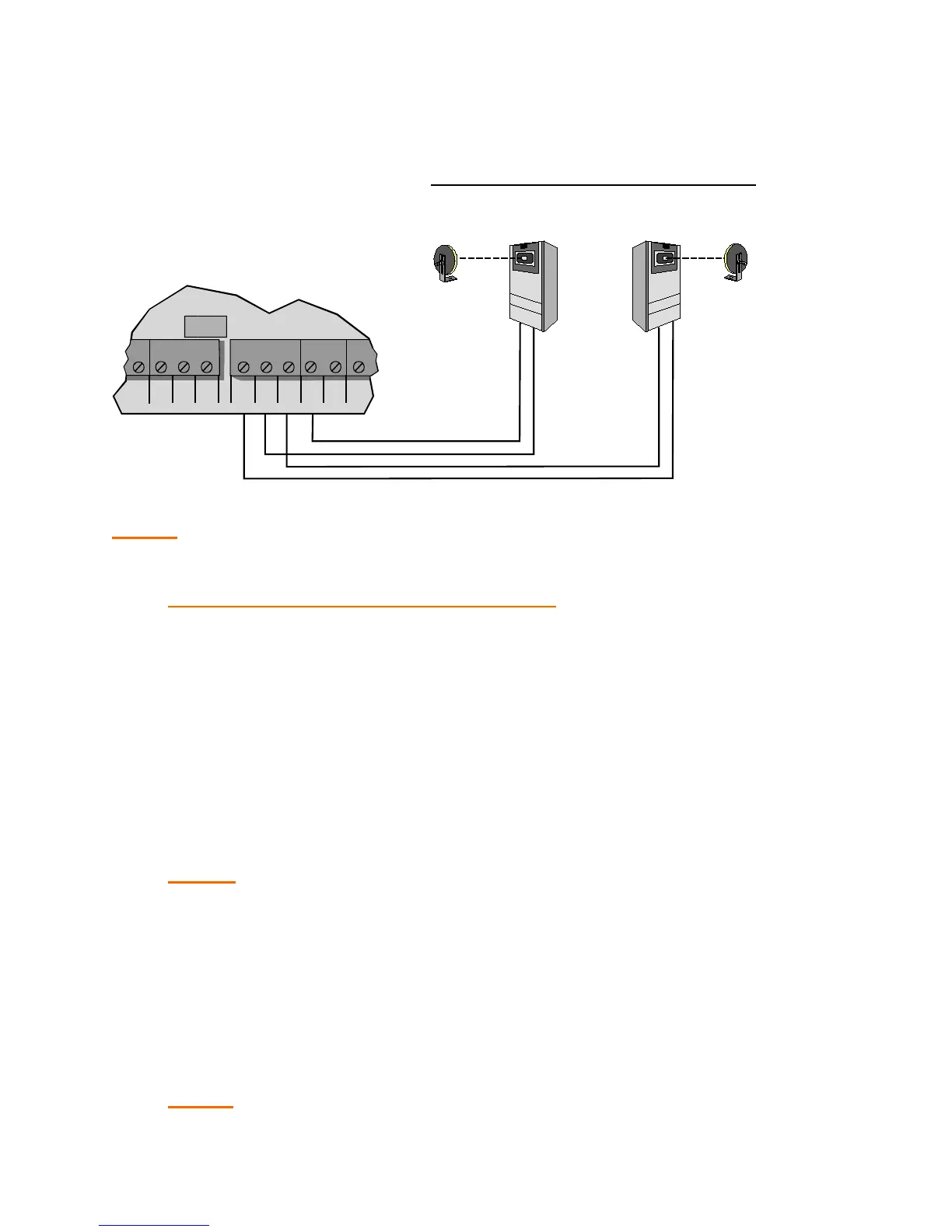
3. Connect NON-CONTACT sensors to the control board as shown
below.
NOTE: Close photocell is connected to “CLO PHO” and “COM” terminals.
Open photocell is connected to “OPN PHO” and “COM” terminals.
AFTER SENSORS ARE CONNECTED:
1. Turn on power.
2
. Make sure the photo-beams are properly aligned per the
manufacturer’s specifications.
3. Te
st the CLOSE obstruction sensing system for proper operation,
by blocking the beam across the gate opening while the gate i
s
r
unning closed.
NOTE: The gate should stop and reverse a short distance and then
stop.
4. Run operator to close limit.
5
. Test the OPEN obstruction sensing system by blocking the beam
mounted at the back area of the gate while the gate is running
open.
NOTE: The operator should repeat the stop and reverse procedure.
TB2
NON CONTACT SENSOR CONNECTION
Close Photocell
Sensor
Open Photocell
Sensor
ReflectorReflector
OPN
CLO
STO
COM
COM
COM
OP
N
PHO
CLO
PHO
SHW