READ THESE STATEMENTS CAREFULLY AND FOLLOW THE
INSTRUCTIONS CLOSELY!
The Warning and Caution boxes throughout this manual are there to protect
you and your equipment. Pay close attention to these boxes as you follow the
manual.
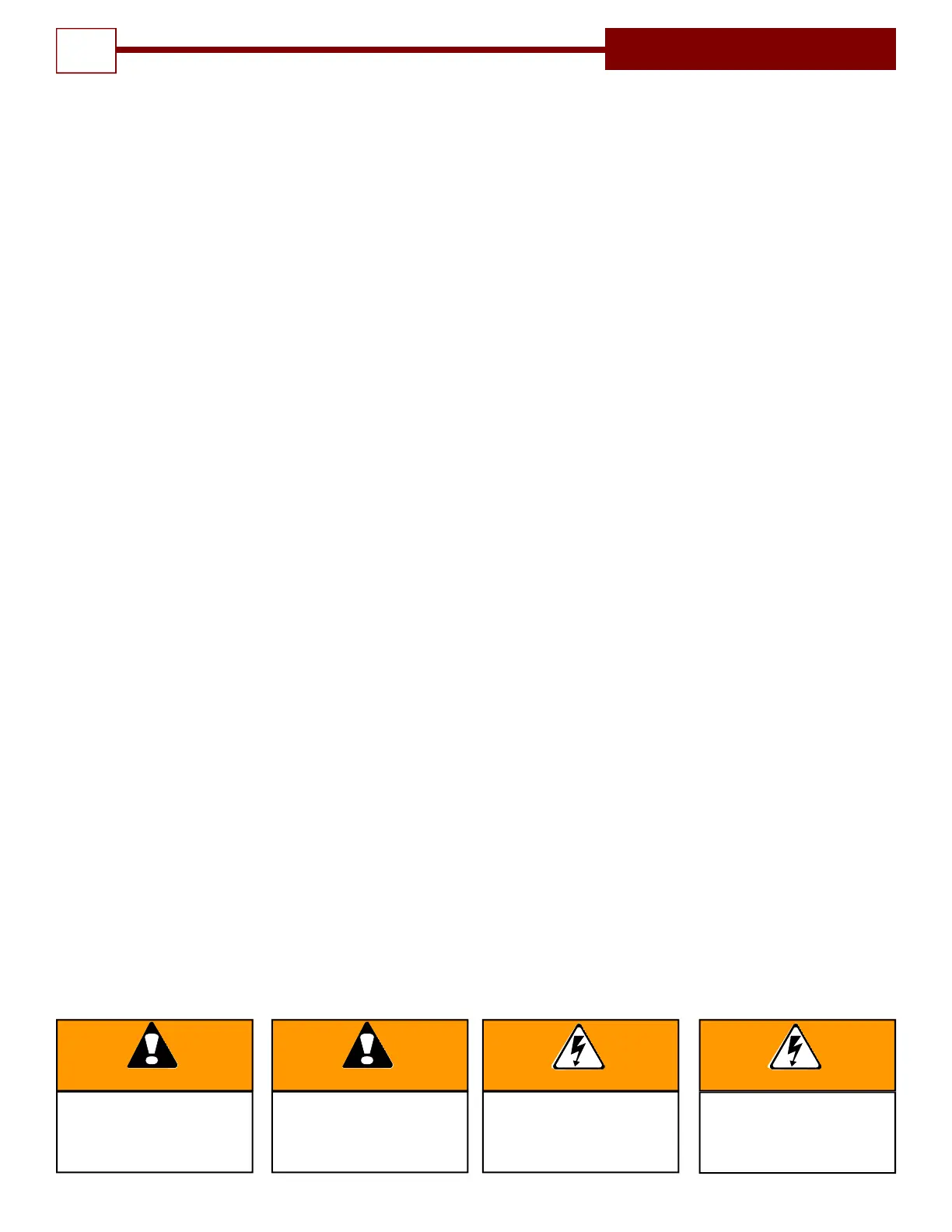
WARNING
Indicates a MECHANICAL hazard
of INJURY OR DEATH. Gives
instructions to avoid the hazard.
CAUTION
Indicates a MECHANICAL hazard
of DAMAGE to your operator or
equipment. Gives instructions to
avoid the hazard.
Indicates an ELECTRICAL
hazard of INJURY OR DEATH.
Gives instructions to avoid the
hazard.
WARNING CAUTION
Indicates an ELECTRICAL hazard
of DAMAGE to your operator or
equipment. Gives instructions to
avoid the hazard.
TABLE OF CONTENTS
2
Model SL Slide Door Operator Applications– Product Features ....................................................….3
Preparation ........................................................................................................................................... 4-8
Component Identification Pictorial - Figure 1
....................................................................... 4
Important Installation Notes (Things To Do Before/During Installation)............................. 5
Component Identification Listing - Table 1 ........................................................................... 5
Rail/Chain Assembly Instructions - Figure 2, 2A.………………………………………………..6
Trolley Assembly Instructions - Figure 3A,.……………………………..………………….........7
Operator Assembly Instructions- Figure 4,5A .................................................................... ..8
Operator Installation ............................................................................................................................... 9
Chain Routing- Figure 6 .......................................................................................................... 9
Hanger Installation- Figure 7,7A ………….. ………………………………………………. ....... 10
Hanger Layout - Figure 8,9 .................................................................................................... 12
Mounting Disconnect Assembly - Figure 10,11,12 .............................................................. 13
Setting The Limits - Figure 13 ............................................................................................... 14
Electrical Wiring Instructions................................................................................................ 15
Field Wiring - Figure 14.......................................................................................................... 16
Operation and Adjustment Instructions.............................................................................................. 17
Clutch Adjustment - Figure 15 ............................................................................................... 18
Brake Adjustment……………………………………………………………………………………..19
Fire Door Disconnect Installation .......................................................................................... 20
Testing...................................................................................................................................... 22
Maintenance .......................................................................................................................................... 23
Trouble Shooting................................................................................................................................... 24
Warranty................................................................................................................................................. 25