Slide Assembly
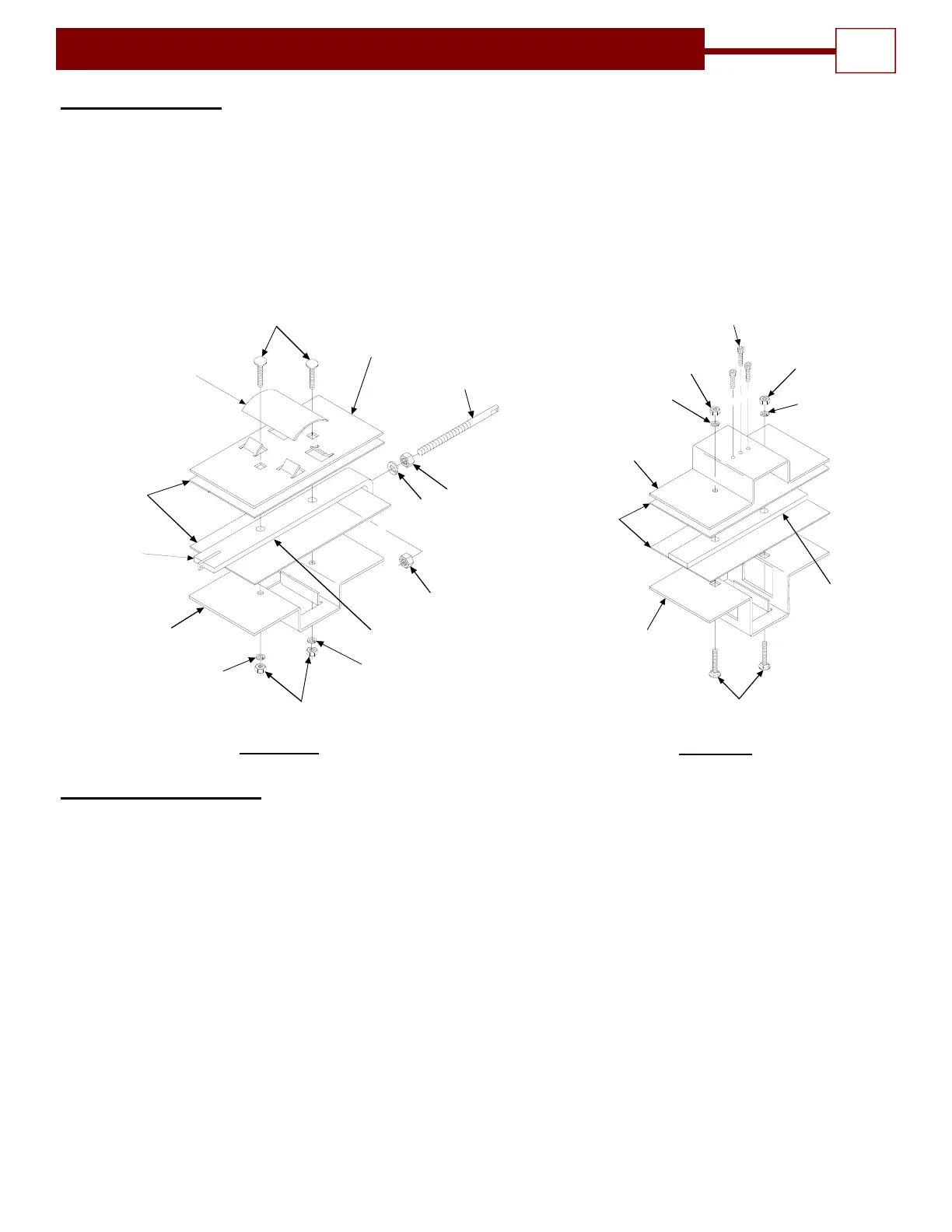
1. Assemble top plate, lower drive plate, center drive bar and two nylon inserts using two 5/16 x 1 ¼
carriage bolts, two 5/16 lock washers and two 5/16 hex nuts as shown in Figure # 3A.
2. Install 3/8 chain take-up bolt into slide assembly using one 3/8 lock washer and two 3/8 hex nuts
as shown in Figure # 3A. (DO NOT TIGHTEN NUTS)
3. For Bi-Part Slide assembly see figure 3B.
INSTALLATION INSTRUCTIONS
7
5/16 X 1-1/4"
CARRIAGE
BOLTS
TOP PLATE
TAKE UP
BOLT
3/8" HEX NUT
3/8" LOCK
WASHER
3/8" HEX NUT
5/15" LOCK
WASHER
5/15" LOCK
WASHER
5/16" HEX NUTS
NYLON INSERTS
CENTER BAR
NYLON CHAIN
DEFLECTOR
CENTER
DRIVE BAR
LOWER
DRIVE PLATE
FIGURE 3A
3/8" LOCK WASHER
NYLON
INSERT
BI-PART TROLLEY
UPPER DRIVE
PLATE
#10 SOCKET HEAD
CAP SCREWS
(3)
3/8" HEX NUT
3/8" LOCK WASHER
3/8" HEX NUT
TROLLEY
CENTER
GUIDE
DEEP
ENGAGEMENT
LOWER DRIVE
PLATE
5/16 X 1-1/4" LG.
CARRIAGE BOLTS
FIGURE 3B
Operator Assembly
1. Install trolley slide assembly on track assembly with chain take-up bolt (7) pointing away from end
of track where power head (8) will be mounted as shown in Figure # 4. Note: If Bi-part
installation, slide Bi-Part trolley slide on first.
2. Mount power head to track assembly using four 3/8 x ¾ long hex head bolts, four 3/8 lock
washers and four 3/8 hex nuts, as shown in Figure # 4.
3. Turn operator assembly over and back off chain adjustment nut to the end of the threads on chain
take-up bolt (7). See Figure # 5.
4. Layout drive chain (9) next to operator assembly work surface.
5. Thread one end of the operator drive chain around operator drive sprocket and connect to the
drive tab on the trolley slide assembly with a chain connecting link (10). See figure 5A and figure
6.
6. Thread the other end of the drive chain (9)around the idler roller assembly (3).See Figure #6.
7. Pull drive chain (9) tight up to trolley slide assembly; mark link that lines with hole on chain take
up bolt on slide assembly and cut drive chain to length. Note: If installing a bi-part operator,
drive chain (9) must pass through Bi-Part slide assembly (15) before being connected to
chain take up bolt (7) on standard slide assembly (5). See figure 5B and figure 6.