8
INSTALLATION INSTRUCTIONS
Operator Assembly
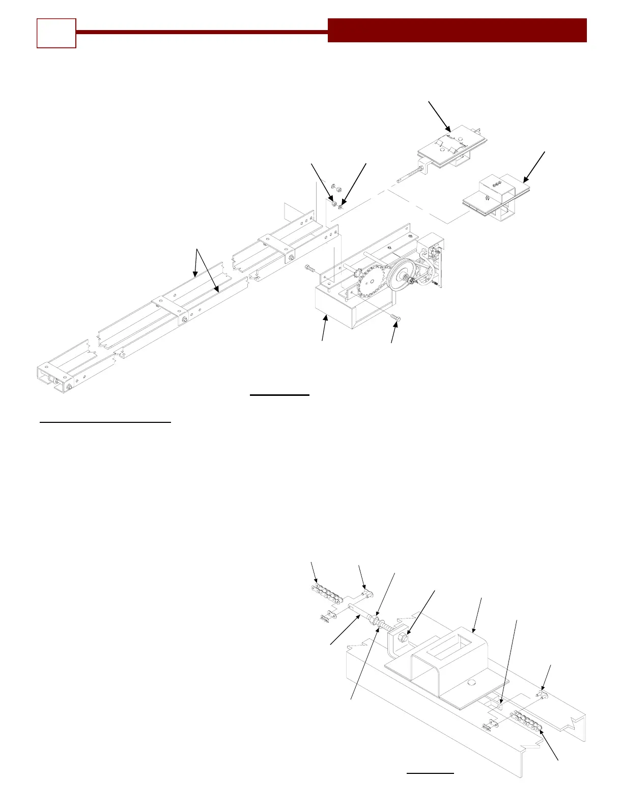
8. Attach cut end of drive chain (9) to chain take up bolts on trolley traveler assembly with a chain
connecting link. See figure 5A.
9. Adjust chain tension using adjusting nut on chain take up bolt, to remove excess slack. See
Figure # 5A.
10. Secure adjustment using lock washer and lock nut on chain take up bolt. See Figure # 5A.
Note: Leave Bi-Part slider carriage free at this time.
11. Bolt the hanger bracket angles together as
shown in Figure 7 to form mounting brackets.
Attach the mounting brackets to the track
spreader brackets, using the 3/8” bolts, lock
washers, and nuts. (See figure 7A) Do not
tighten as the distance from the wall to the
track will have to be adjusted later.
POWER
HEAD
(4) 3/8"
HEX HEAD
BOLTS
(4) 3/8"
LOCK
WASHERS
(4) 3/8"
HEX BOLTS
TRACK
ASSEMBLY
-5
STANDARD
TROLLEY SLIDE
ASSEMBLY
-15
BI-PART TROLLEY
SLIDE ASSEMBLY
(WHEN REQUIRED)
FIGURE 4
DRIVE
CHAIN
-9
CHAIN
CONNECTING LINK
-10
LOCK NUT
-7
CHAIN
TAKE-UP
BOLT
LOCK
WASHER
-9
CHAIN
CONNECTING LINK
-10
TROLLEY
ASSEMBLY
-5
DRIVE TAB
CHAIN
ADJUSTING
NUT
FIGURE 5A