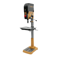
How to prevent wood splinters when using Powermatic Power Tool?
- CChelsea GonzalezSep 7, 2025
To address wood splinters on the underside of your Powermatic Power Tool work piece, place a scrap board beneath the work piece to prevent splintering.

How to prevent wood splinters when using Powermatic Power Tool?
To address wood splinters on the underside of your Powermatic Power Tool work piece, place a scrap board beneath the work piece to prevent splintering.
What does ERR-1 mean on a Powermatic Power Tool?
ERR-1 on your Powermatic Power Tool indicates an overload protector. Press the off button to clear the error code, then press on to restart the machine.
What does ERR-6 mean on a Powermatic Power Tool?
ERR-6 on your Powermatic Power Tool indicates over voltage. Press the off button to clear the error code, then press on to restart.
What does ERR-7 mean on a Powermatic Power Tool?
ERR-7 on your Powermatic Power Tool indicates low voltage. Press the off button to clear the error code, then press on to restart.
What does ERR-2 mean on a Powermatic PM2820EVS Power Tool?
ERR-2 on your Powermatic Power Tool indicates a motor revolution sensor issue. Replace the motor.
| Brand | Powermatic |
|---|---|
| Model | PM2820EVS |
| Category | Power Tool |
| Language | English |
Details dimensions and layout of mounting holes on the drill press base.
Lists all items included in the product packaging for assembly.
Instructions for removing factory rust protectant from metal surfaces.
Lists necessary tools for assembling the drill press.
Step-by-step guide for assembling the drill press components.
Procedures for safely lifting and attaching the drill head to the column.
Steps to ensure the drill press table and insert are properly leveled.
Instructions on how to install the arbor and chuck onto the spindle.
Critical safety information regarding proper grounding of the machine.
Guidelines on selecting appropriate extension cords for the drill press.
Adjusting table height, swing, and tilt for various drilling operations.
Steps for safely removing the chuck and arbor from the spindle.
Setting the depth stop for repetitive drilling to a specific depth.
How to lock the quill in a lowered position to prevent retraction.
Description of the work stop used for consistent drilling length.
How to align the laser guide for accurate hole placement.
Information on the drill press's LED work lights.
Explanation of the main power switch, safety key, and indicator light.
Steps for correctly inserting and tightening drill bits into the chuck.
Guidance on securing workpieces to the table to prevent movement during drilling.
Pre-operation checks to ensure the drill press is safe and ready.
Factors influencing the correct spindle speed selection for different materials.
Common problems and their solutions related to the drill press's mechanics and electrics.
Explanation of error codes displayed on the digital readout and their causes.
Diagram showing the exploded view of the gear box assembly.
Detailed list of parts for the gear box assembly with index numbers.
Diagram showing the exploded view of the quill and laser assembly.
Detailed list of parts for the quill and laser assembly with index numbers.
Diagram showing the exploded view of the control panel components.
Detailed list of parts for the control panel with index numbers.
Diagram showing the exploded view of the top cover and PCB assembly.
Detailed list of parts for the top cover and PCB assembly with index numbers.
Diagram showing the exploded view of the work table assembly.
Detailed list of parts for the work table assembly with index numbers.
Diagram showing the exploded view of the fence assembly.
Detailed list of parts for the fence assembly with index numbers.
Diagram showing the exploded view of the column assembly.
Detailed list of parts for the column assembly with index numbers.
 Loading...