PowerMax Pool Heater
Page 21
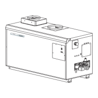
Figure 7. Typical Gas Train Configuration.
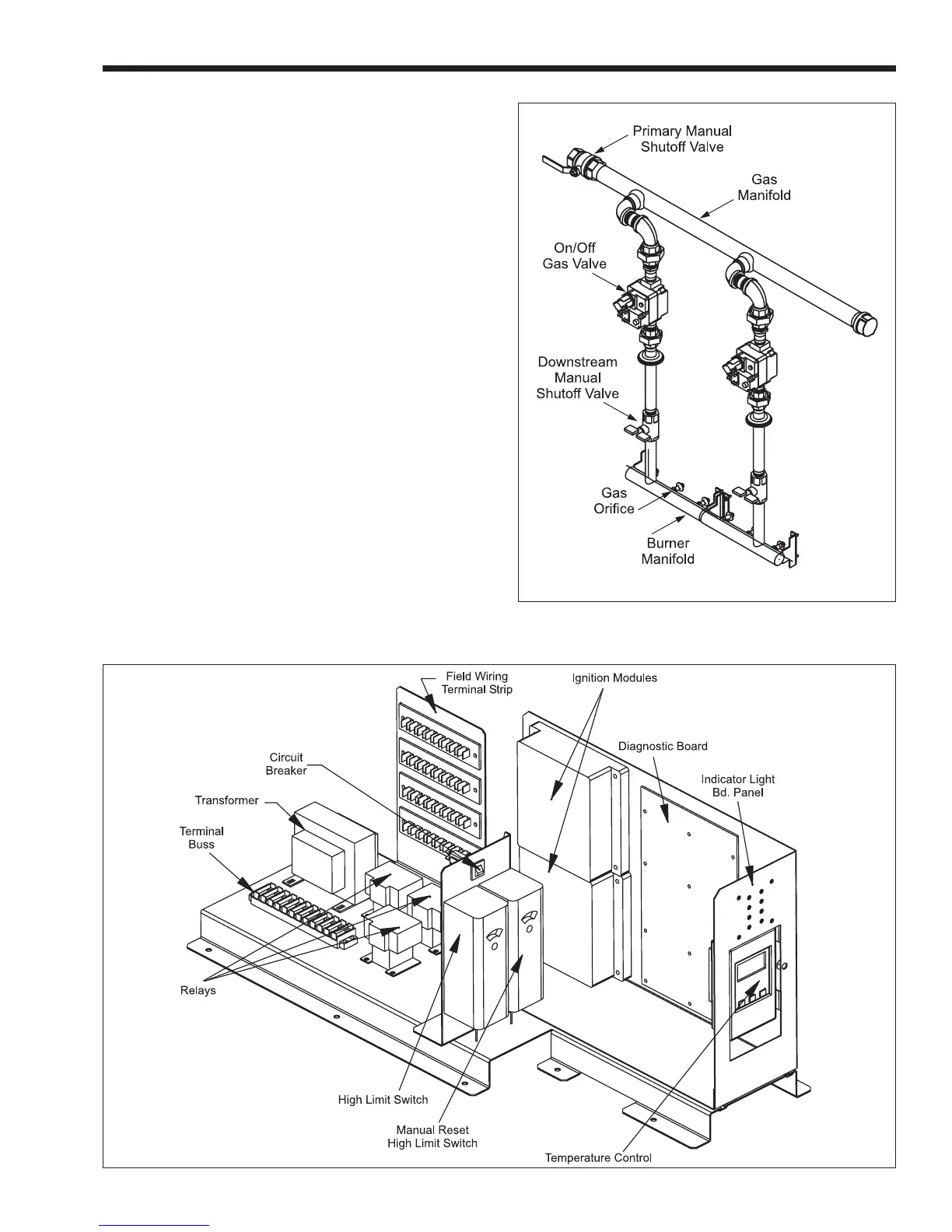
Figure 8. Typical Control Panel.
8.5 Troubleshooting the Pool Heater
Temperature Control
With a Voltmeter, test for 24 VAC between
terminals 1 & 2 on the 10 pin connector. Check that
the sensor temperature is lower than the setpoint
temperature by at least the differential setting. If this is
true, check that there is 24 VAC at the yellow wire on
the 4 pin connector. If there is not 24 VAC, check that
the high limit is not open. If there is 24 VAC at the
yellow wire on the 4 pin connector and not at the light
blue wire on that connector, replace the control.
8.6 Troubleshooting PowerMax Controls
The PowerMax series consists of three models
with one ignition module (500, 750 & 1000) and four
models with two ignition modules (1250, 1500, 1750
and 2000).
A diagnostic panel, that includes test points, as
well as diagnostic lights, is provided in the control
module. It is located on the right side of the module,
behind the display. To access, remove the retaining
screws from the display cover panel and remove it.
Grasp the control module at its base and pull it
outward. Ladder diagrams are shown in Figures 12
and 13.
Figure 12 shows the diagram for the 500, 750 &
1000. These have one blower and one ignition