2.2Themainscreen
Thefigure2.2.1showthemainscreen;thisscreenappearsafterashortpresentationwhentheuserpowersonthe
amplifier.Inthefirstline,afterpoweron,thewriting"WAIT"appears;ifthesystemparametersarenormal,thewriting
arereplacedwith"READY".Duringthenormaloperationthecontrollermonitorsthesystemparameters.Ifa
paramenterisoutofrange,thecorrespondentcodeerroriswrittenontheLCDmeteroftherelativechannelinthe
thirdline;iftheabnormalparameterisassociatedtobothchannel,theerrorcodeiswritteninthecenter.
2Setupandsettings
2.1Introduction
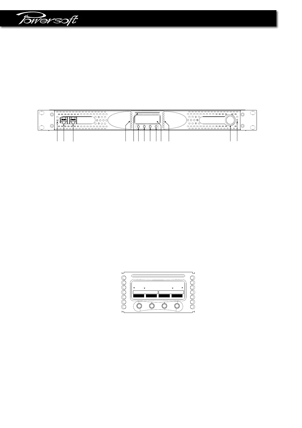
ThefigurebelowshowsthefrontpanelofDIGAMKSeries. Thefrontpanelcontrols,inconjuctionwiththegraphic
LCDdisplayabovethebuttons,givetotheuserthetotalcontrolanddetailedinformationaboutthestatusofthe
amplifier.Eachpushbuttonhasmultiplefunctionsandthedisplayshowsthecurrentactivefunctionforeachbutton.
Readcarefullytheinstructionsbelowthathelpyoutomanagethefunctionsoftheamplifier.
figure2.1.1
TheLEDbarscanfunctionasoutputvoltageoroutputcurrentmeters;inthefirstcasetheLCDmetersfunctionas
outputcurrentmeter,viceversainthesecondcase.
TheLEDbarshavediagnosticfunctionalso;aflashingyellowLEDindicatesacriticrangeoftemperature(from80°C
to85°C)ofthepowerdevicesonthecorrespondingchannel,ifthisLEDislightingconstantly,thetemperatureisabove
85°C. A lightingconstantlyredLEDindicatesthatthecorrespondingchannelisunderprotectionandinthiscasethe
writing"PROT"appearsinthefirstlineofthedisplay.
ThefirstgreenLEDatthebottomsideoftheLEDbarindicates,
whenlighted,thepresenceofinputaudiosignalabove-60dBVonthecorrespondingchannel;the2nd,3rdand4th
LEDintheascendingorderindicatesanoutputlevelof-3dB,-6dBand-10dBrispectively. ThegreenLEDswillbe
lightedduringnormalworking. TheyellowLEDwilllightat-1dB.Iftheleveloftheaudiosignalreachthechannel
outputcapability,redLEDwillbetriggered.
lock
mute mute
menu
CH1 READY READY CH2
V I
I
V
figure2.2.1
13
A
B
C
D E F
G
H I
J
K
A-Ethernetplugn°1
B-Ethernetplugn°2
C-V/I-meterchanneln°1
D-Smartcardreader
E-Functionbuttonn°1
F-Functionbuttonn°2
G-Functionbuttonn°3
H-Functionbuttonn°4
I-GraphicLCDdisplay
J-V/Imeterchanneln°2
K-Powerswitch
L-Grillfilterscrews
L
L