19
DigiMod 500 1000 1500 2000HV 1000NPS | SERVICE MANUAL
INDEX
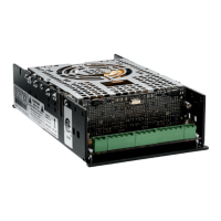
Signal
Signal
CH1 Protect
CH2 Protect
+5Vdc
+12Vdc
-12Vdc
Indicated on (Fig. 16) are the Control Board LEDs and
their functions.
(Fig. 16)
Connect the power cable to the CN1 connector located
on the opposite side of the control board.
Check if all 3 green LEDs are on.
Connect a function generator or a cd player to the module
through the CN12, CN11 connectors.
Select an audio track from the Powersoft Test CD, or a
Sine wave test tone.
Verify the presence of audio signal by probing on the
CN7, CN3 connectors with an oscilloscope.
Signal Ground 2
Signal Ground 1
Balanced Input +2
Balanced Input -2
Balanced Input -1
Balanced Input +1
CH2 OUT +
CH2 OUT -
CH1 OUT +
CH1 OUT -
Indicated on (Fig. 17) is the pin out of the CN7, CN12,
CN11, CN3 connectors.
(Fig. 17)
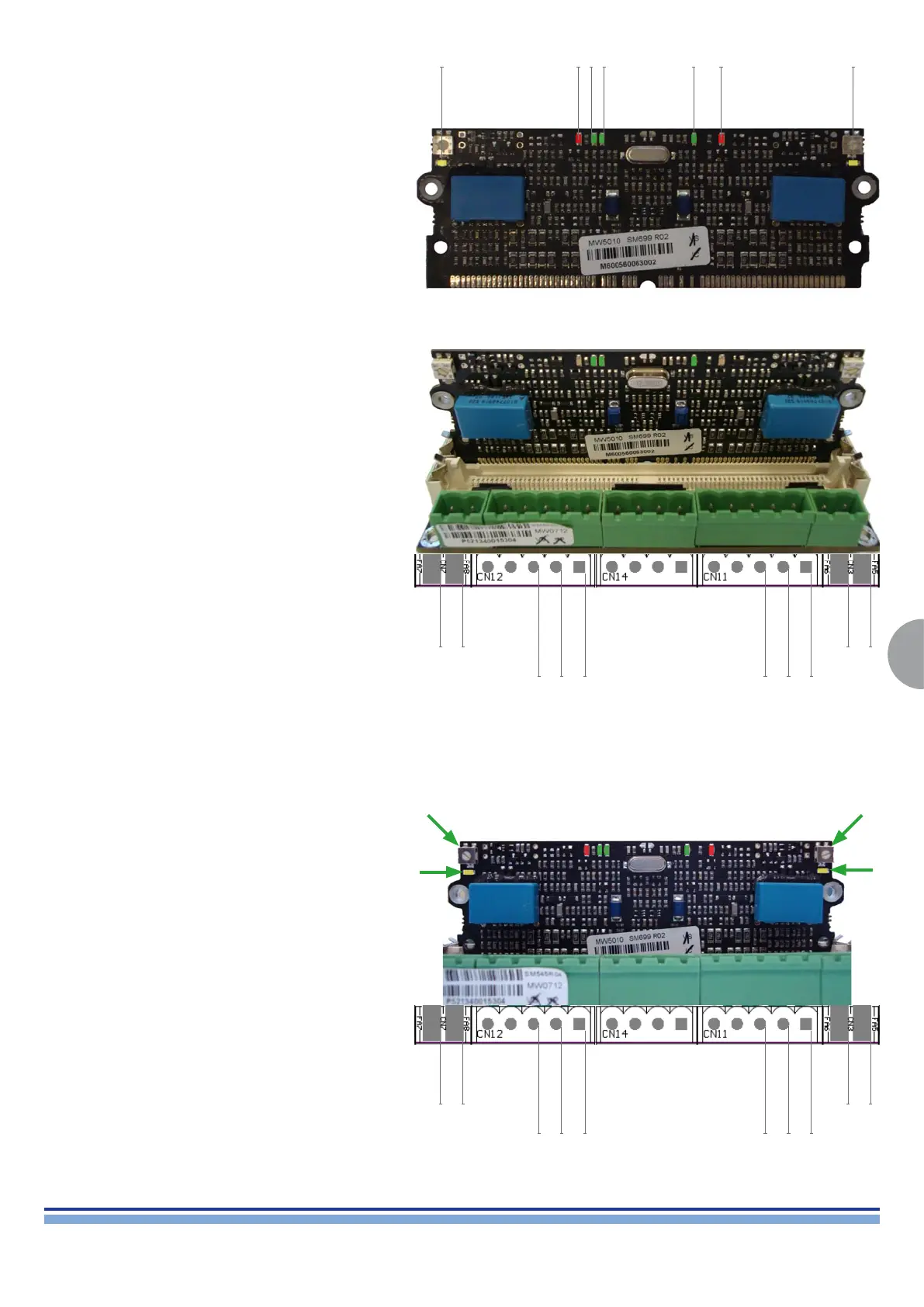
8. Output Current Offset Calibration Procedure:
Signal Ground 2
Signal Ground 1
Balanced Input +2
Balanced Input -2
Balanced Input -1
Balanced Input +1
CH2 OUT +
CH2 OUT -
CH1 OUT +
CH1 OUT -
Connect a Signal Generator/Cd Player to the module via
the CN12, CN11 Connectors.
Supply a 1Vrms 1 KHz Sine Wave or play the rst track
of the Powersoft Test CD, in which case check with a
multimeter if the output signal of the cd player is 1Vrms.
Located on both top corners of the Control Board are the
Output Current Offset Trimmers, adjust them by turning
the at head screw until the yellow LEDs below turns off.
Portrayed on (Fig. 18) are the CH1, CH2 inputs, the
Output Current Offset Trimmers and the Yellow LEDs.
(Fig. 18)
 Loading...