EasyManua.ls Logo

powersoft Duecanali 804 User Manual

powersoft Duecanali 804
44 pages
To Next Page IconTo Next Page
Page #1 background imageLoading...
Page #1 background image
Keep this manual
for future reference

Duecanali Series

Serie Duecanali & Duecanali / Duecanali & Duecanali Serie
Duecanali & Duecanali Série / Serie Duecanali & Duecanali
󰋸󰏼󰋸󰏼󰑜󰑧
Duecanali & Duecanali / Duecanali & Duecanali 系列
USER GUIDE
GUIDA UTENTE / BENUTZERHANDBUCH
MODE D'EMPLOI / GUÍA DEL USUARIO
GUIA DE USARIO / 󰊶󰏼󰒎󰏼󰈉󰏼󰐘󰋸󰈛󰉰󰊶󰐘
ユーーガ / 快速指南
DO000209.05 R01
Duecanali 804
Duecanali 1604
Duecanali 2404
Duecanali 4804



Duecanali 804 DSP
Duecanali 1604 DSP
Duecanali 2404 DSP
Duecanali 4804 DSP
Duecanali 6404 DSP




Duecanali 804 DSP+D
Duecanali 1604 DSP+D
Duecanali 2404 DSP+D
Duecanali 4804 DSP+D
Duecanali 6404 DSP+D




Duecanali 804 DSP+
Duecanali 1604 DSP+
Duecanali 2404 DSP+
Duecanali 4804 DSP+
Duecanali 6404 DSP+




Duecanali Series

Quattrocanali
2404
Duecanali
1604

Other manuals for powersoft Duecanali 804

Question and Answer IconNeed help?

Do you have a question about the powersoft Duecanali 804 and is the answer not in the manual?

powersoft Duecanali 804 Specifications

General IconGeneral
Channels2
Output Power (8 ohms)400 W
Output Power (70V)800 W
Output Power (100V)800 W
THD+N< 0.1%
Signal to Noise Ratio> 100 dB
Input Impedance20 kΩ
Dimensions19" x 1.75"
Frequency Response20Hz - 20kHz (±0.5dB)

Summary

Duecanali Series Quattrocanali Series User Guide

Important Safety Instructions

Common Symbols and Meanings

Explains common symbols used in the manual for safety and operation.

Safety Warnings and Precautions

Lists critical safety precautions for operating the equipment.

Warranty and Technical Service Information

Details on product warranty coverage and service procedures.

Regulatory Compliance Statements

European Union Compliance

Statements regarding European Union regulatory compliance like WEEE.

USA FCC Compliance

Statements regarding US Federal Communications Commission compliance.

Canadian Compliance

Statements regarding Canadian regulatory compliance.

EC Declaration of Conformity

Formal declaration of product conformity to EC directives.

Preliminary Operations and Features

Package Contents and Installation Location

Details the amplifier's package contents and optimal installation environment.

Cooling System and Ventilation

Explains the amplifier's cooling system and ventilation requirements.

Energy Save and Breaker Save Modes

Describes power saving features and current draw reduction.

Remote On/Off and Gain Selection

Instructions for remote control and input signal gain adjustment.

Signal Connections and Level Adjustment

Information on signal grounding, analog inputs, and remote level control.

Digital Audio, Networking, and System Configuration

Digital Audio Input and Ethernet Connectivity

Connecting digital audio sources and remote control via Ethernet.

Output Connections and Load Configuration

Details on speaker connections and load impedance settings.

Hi-Z and Lo-Z Load Operation Modes

Guide for using high-impedance (70V/100V) and low-impedance (2Ω) loads.

Networking and IP Addressing

Overview of network topology, IP settings, and ArmoníaPlus software.

Input Selection and Backup Policy

Selecting audio inputs and implementing signal backup.

Output Load Monitoring

Monitoring load impedance and performance via ArmoníaPlus.

System Diagnostics and Monitoring Features

Diagnostics, GPO, and Alarm Reporting

Using GPO outputs for fault reporting and alarm signals.

Self Check Procedure

Procedure for testing the amplifier's status and reporting faults.

Pilot Tone Monitoring for Backup

Monitoring pilot tone parameters to trigger backup policies.

Hardware Overview and Panel Components

Rack Installation Location and Cooling

Guidance on rack placement, cooling, and ventilation.

Exposing the Control Panel and Dimensions

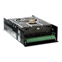
How to access controls and physical specifications of the unit.

Front Panel Layout and Controls

Description of the front panel layout, including buttons and LEDs.

Rear Panel Connectors and Switches

Overview of connectors, dip switches, and ports on the rear panel.

Output Section and AC Mains Input

Details on output connectors and the AC power input.

LED Indicators and System Status Interpretation

LED Bars for Signal Metering

Explanation of LED bars used for signal level indication.

System Status LED Bar Interpretation

Meaning of LEDs indicating overall system status and health.

Operating Mode and Channel Status LEDs

Interpretation of LEDs for operating modes and channel status.

Control Panel Button Actions Summary

Detailed actions and effects of control panel buttons.

Related product manuals