4 | Duecanali - Quattrocanali
Location
Install your Duecanali/Quattrocanali Amplier in well ventilated rack
cabinets.
Secure both front and rear brackets to the rack.
Connect the AC Mains connector to a circuit breaker.
Install the amplier far from EMF emitting devices.
Avoid placing the amplier close to heat generating sources.
Cooling
The ventilation openings must not be impeded by any item, keep a
distance of at least 50 cm from the front and rear ventilation openings
of the amplier.
Duecanali/Quattrocanali implements a forced-air cooling system to
maintain constant operating temperatures. Air enters from the front
panel, exiting at the back of the amplier.
The cooling system features variable-speed DC fans controlled by
the heat sink mounted sensors. This ensures that fan noise and
internal dust accumulation are kept to a minimum.
In the rare event of overheating, sensing circuits shut down
all channels until the amplier cools down to a safe operating
temperature. Normal operation is resumed automatically without the
need for user intervention.
Duecanali/Quattrocanali ampliers can be stacked one on top of the
other, leave one rack unit empty every four to guarantee adequate
air ow.
Cleaning
Use a dry cloth for cleaning the chassis and the front panel. Air lter
cleaning should be scheduled in accordance with the dust levels in
the amplier’s operating environment.
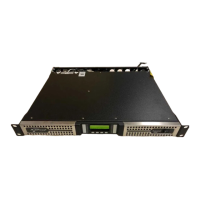
In order to clean the vent lters remove the front cover by rmly
gripping the outermost silver panels and pull them outwards
Use compressed air to remove the dust from lters, or wash it with
clean water (let the lter dry thoroughly before reinstalling them).
Package list
The box contains the following:
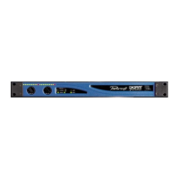
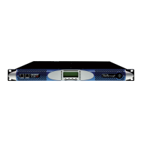
1x Duecanali Series amplier.
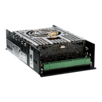
1x Phoenix MC 1,5/4-ST-3,81 - 1803594 plug
2x Phoenix MC 1,5/6-ST-3,81 - 5447900 plug
1x Phoenix PC 5/4-STF1-7,62 - 177859 plug
1x IEC power cord
1x quick guide
OR
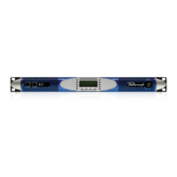
1x Quattrocanali Series amplier.
1x Phoenix MC 1,5/4-ST-3,81 - 1803594 plug
2x Phoenix MC 1,5/12-ST-3,81 - 1803675 plug
1x Phoenix PC 5/8-STF1-7,62 - 177891 plug
1x IEC power cord
1x quick guide
Preliminary operations
Signal Grounding
There is no ground switch or terminal on the Duecanali/Quattrocanali
Series ampliers. The unit’s signal grounding system is automatic. In
order to limit hum and/or interference entering the signal path, use
balanced input connections.
In the interests of safety, the unit MUST always operate with electrical
safety earth connected to the chassis via the dedicated Protective
Earth
wire.
Connections
Once properly powered (power cord inserted, sectioning breaker
closed), the system can be either ON or in STANDBY mode
depending on its state at latest power off.
In order to toggle the amplier between ON and STANDBY keep
pressed the power button for 3 seconds. Please consider that
the operating condition can be modied by the REMOTE ON and
REMOTE OFF conguration.
Switching the amplifier On and Off
The Duecanali/Quattrocanali Series ampliers can operate with
different gain applied to the input signal. This feature is designed to
match the voltage of the input signal.
A proper combination of the position of two GAIN switches on the
rear panel sets the operating gain of the amplier
Gain selection
The Smart Rails Management technology implemented in the power
supply unit allows to reduce the power consumption when the input
signal falls under a dened threshold.
When On, Energy Save is active on each channel independently.
If the signal is missing for more than 30 minutes on all channels, the
auto standby is applied and the main PSU is turned off to further
save energy (
Time out time is selectable via Armonía in DSP+D Versions). Normal
operation is resumed in a matter of milliseconds when an incoming
signal is detected.
In order to activate the Energy Save feature, operate the NRG SAVE
dip switch on the rear panel.
Energy Save
Remote ON/OFF is available through the dedicated terminals on the
rear panel.
Both terminals respond to the differential voltage between the
contacts: a voltage difference in the range 5 V
DC
- 24 V
DC
triggers
the control. Any voltage exceeding 28V
DC
may damage the input
circuitry.
The couple of terminals act depending on the actual state of the
amplier, in accordance with the following table.
REMOTE ON REMOTE OFF AMPLIFIER STATE
Vdiff ≥ 5V Any Force Turn ON
Vdiff < 3V Vdiff ≥ 5V Force Turn OFF
Vdiff < 3V Vdiff < 3V
No Change
(Keep either standby or in current state)
Remote On/Off
This feature may be activated when the power grid is unable to
provide enough current to continuously drive the loads, or when the
number of amplier connected to the same outlet is such that one
can reach the critical power absorption of the line.
When activated, the Breaker Save halves the maximum continuous
current absorption from the mains. This slightly reects on the overall
performance of the system, reducing the available output power.
In order to activate the Breaker Save feature, locate the BRK SAVE
switch on the rear panel.
Breaker Save
The level of each channel can be remotely adjusted by means of a
linear 10 kΩ potentiometer connected to the input LEVEL connector.
When the CH1 MSTR switch is in the OFF position the remote level
potentiometers work independently on each separate channel.
When the CH1 MSTR switch is in the ON position the remote level
potentiometer of channel 1 acts as a master level, controlling the
volume of both channels.
The remote level controls are in series with the level adjustment
knobs in the front panel.
Remote Level adjustment
Analog input connections are made via the Phoenix MC 1,5/6-ST-
3,81 5447900 connector.
Analog Audio Input connections
Duecanali/Quattrocanali Series ampliers implement an universal
switching mode power supply with power factor correction operating
in the range from 100 V
AC
up to 240 V
AC
±10%.
AC mains connection is in the rear panel through the IEC C20 inlet,
the approved power cord is provided.
AC Mains Supply
 Loading...
