4) Final Checks and Start Up
4.1 Initial Checks
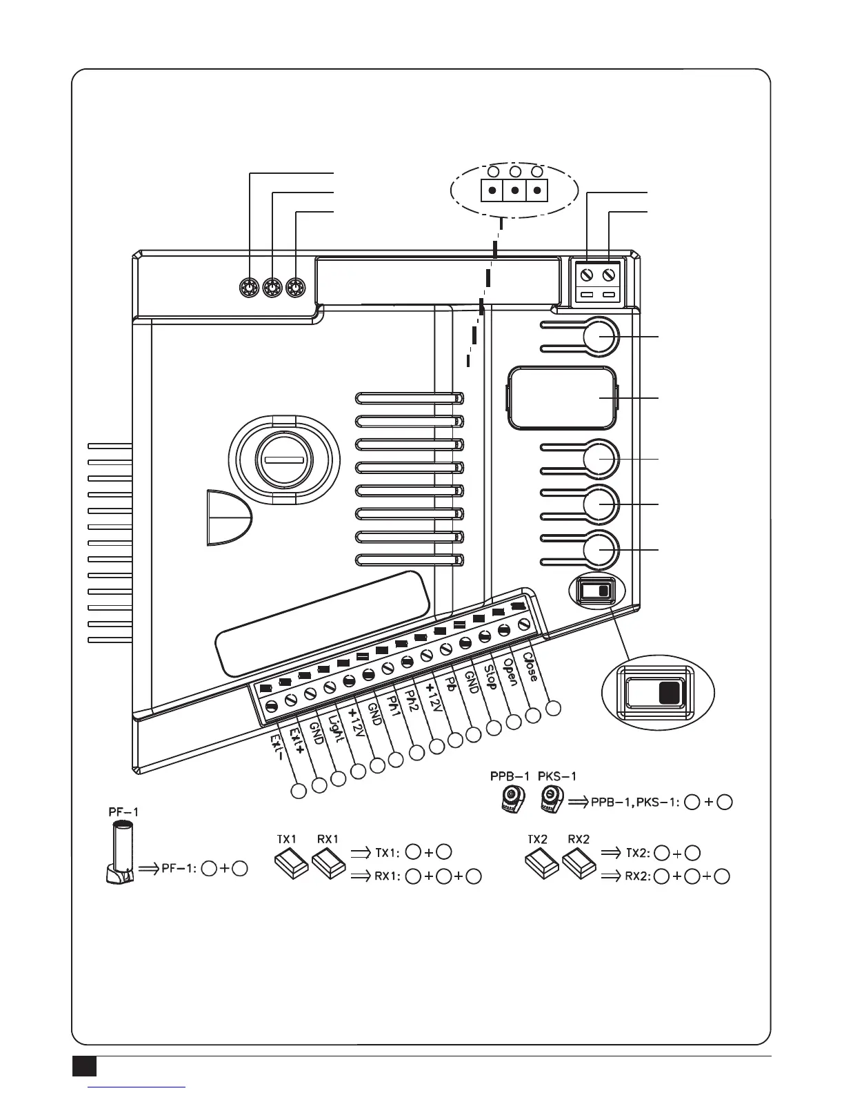
4.1.1 Design of PL600/PL1000 control unit
LED1 Photocells
LED2 Photocells
LED3 RF Learning
3 2
1
Jumper4
RF LEARN
UP
SET
DOWN
ON/OFF
ANT
GND
RF Learn (SW1)
LED Display
UP (SW3)
SET
(SW4)
DOWN (SW5)
SW2
4
5
6
3
1
2
9
10
7
8
11
12
13
14
ON OFF
10
11
6 9
6
9
3
4
6 7 9 6 8
9
If the Led display is in normal performing refer to “4.2.1”, you can control the gate by either transmitters or the button
on the board: “UP”-clockwise moving, “SET”- stop and “DOWN”- Counterclockwise moving.
Notice 1: Reset function- In any condition of gate moving and stop, press SW3 and SW5 (clockwise moving and
counterclockwise moving) for 3 secs, then the LED will display “CLR” meaning “reset successfully”. All functions
including system learning will return to the factory setting and the status before system learning.