INSTRUCTIONS PL600H/PL1000H
13
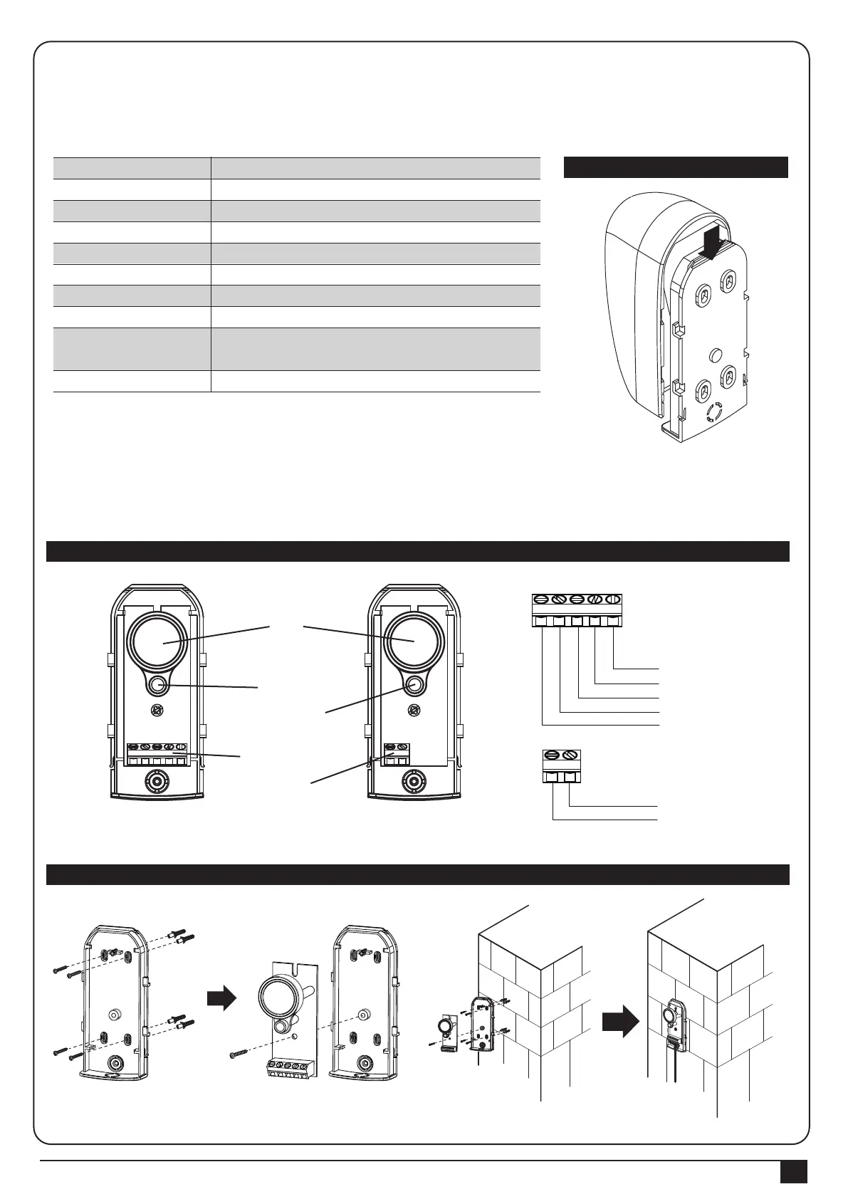
3.3.2 PH-2 Photocells
The safety photocells are security devices for control automatic gates. Consist of one transmitter and one receiver
based in waterproof covers; it is triggered while breaking the path of the beams.
INSTALLATION:
Wire Connection of PH-2 Photocells See figure 4(2)
TX: Connect terminals 1 and 2 on the transmitter with the terminals Ph+ and GND on the PC600 PCB.
RX: Connect terminals 1, 2 and 4 on the receiver with the terminals Ph+, GND and Ph1 on the PC600 PCB.
And use an extra wire to connect terminals 2 and 5 on the receiver as a bridge.
Detection Method
Sensing Range
Input Voltage
Response Time
Emitting Element
Operation Indicator
Dimensions
Output Method
Current Consumption Max
Water Proof
Through Beam
25M
AC/DC 12~24V
100MS
IR LED
Red LED(RX): ON(When Beam is Broken), Green(TX):ON
96*45*43mm
Relay Output
TX: 35MA/Rx: 38MA (When beam aligned properly);
TX: 35MA/ Rx: 20MA (When beam is broken)
IP54
RX
RX
Lens
Beam Alignmnet
Indicator
Power Led
Indicator
Terminal Block
Power
Terminal Block
COM
N.C.
N.O.
GND
DC (12~24V)
GND
DC (12~24V)
TX
TX
SPECIFICATION:
Figure 4(3)
Figure 4(2)
Figure 4(1)
1 2 3 4 5
1 2 3 4 5 1 2
1 2