1. Remove the sealing screw from the pressure test point located
on the side of the gas inlet to the burner head and attach a
pressure gauge. Remove the sample point cover plug from the
outlet flue length and insert a CO
2
measuring instrument.
2. Turn ON the main electricity supply and check that the
following sequence of events occur.
i) Burner fan runs.
ii) Ignition spark is heard.
iii) Main gas valves open and main gas flame is established.
3. Check that the main burner gas pressure agrees with that
stated on the heater data plate. If necessary adjust the main
burner gas pressure (Fig 2) by rotating the adjustment screw
under the cover flap. If the range of adjustment does not allow
for setting of the correct burner pressure the main volume
regulator may also be used. It is recommended that the main
governor adjustment is within 50% to 75% of its range.
4. Measure the CO
2
content of the flue gases. If necessary adjust
the combustion air damper of the burner (Refer to the Burner
Instructions) to obtain a reading of 9.0 - 9.5%
5. Turn OFF the burner, remove pressure gauge and refit sealing
screw in pressure test point and flue sample point cover plug.
5.4.1.3.2 CP-G 400 - 2000
1. Remove the sealing screw from the pressure test point located
on the side of the gas inlet to the burner head and attach a
pressure gauge. Remove the sample point cover plug from the
outlet flue length and insert a CO
2
measuring instrument.
2. Turn ON the main electrical supply and the burner will run
through its sequence until main flame is established. Check that
the main burner gas pressure agrees with that stated on the
heater data plate. If necessary adjust the main burner gas pressure
(Fig 2) by rotating the adjustment screw under the cover flap.
If the range of adjustment does not allow for setting of the
correct burner pressure the main volume regulator may also be
used. It is recommended that the main governor adjustment is
within 50% to 75% of its range.
3. Measure the CO
2
content of the flue gases. If necessary adjust
the combustion air damper of the burner (Refer to the Burner
Supplement) to obtain a reading of 9.0 - 9.5%.
4. Turn OFF the burner. Remove pressure gauge, refit sealing
screw in pressure test point and flue sample point cover plug.
5.4.1.4 Final Soundness Test
1. After making final gas rate checks all joints on the gas controls
assembly must be tested for soundness using leak detection
fluid.
5.4.1.5 Flame Safeguard
1. Whilst the burner is in operation close the gas service valve.
The burner should go to lockout within 1 second.
5.4.1.6 Gas Burner Max. Air Pressure Switch (P2)
Note: Refer to the burner instruction booklet but follow the
steps below.
5. Commissioning & Testing
5.1 Electrical Installation
Checks to ensure electrical safety must be completed by a
competent person.
5.2 Gas Installation (if applicable)
The whole of the gas installation, including the meter, should
be inspected and tested for soundness and purged in accordance
with the recommendations of IGE/UP/1 or IGE/UP1A or
IGE/UP/1B as appropriate.
5.2 Oil Installation (if applicable)
The whole of the oil installation, including the tank, should be
inspected and tested in accordance with the recommendations
of OFTEC.
5.3 Air Distribution System
The system should be checked to ensure that the installation
work has been carried out in accordance with the design
requirements.
Particular attention should be given to the correct arrangement
of delivery ducts and registers, return air ducts and grills and
general adequacy of return air paths.
For CP /*D heaters ensure that the total duct system resistance
does not exceed the available air pressure of the equipment
supplied refer to Table 2 (Page 7). If the duct system resistance
is less than the available air pressure of the equipment supplied
additional resistance must be introduced e.g. by adjustment of
duct outlet nozzles and balancing of the duct system. Conversely
if the duct system resistance is greater than the available air
pressure of the heater supplied the system resistance must be
reduced.
5.4 Lighting the Air Heater
5.4.1 Gas Fired Heaters
Note: Refer also to the burner instruction booklet supplied with
the heater. This provides information on adjusting the burner,
setting up the air pressure switches, system checks and fault
finding detail.
5.4.1.1 Gas Controls Assembly - Soundness Check
1. Ensure the gas service valve at the inlet to the gas controls
assembly is shut.
2. To prove soundness of the first main safety shut-off valve:-
a) Connect pressure gauge to the inlet pressure test point
on the main valve block or inlet pipework.
b) Open gas service valve and allow pressure to stabilise
before shutting it again. The valves are sound if no pressure
drop is observed. If a pressure drop is observed do not
proceed until the fault has been rectified. Remove pressure
gauge and refit sealing screw in pressure test point.
5.4.1.2 Sequence Check
1. Ensure that the gas service valve is closed and that the main
electrical supply to the heater is switched off.
2. Start the burner by setting the time clock and thermostat to
call for heat or complete the external control circuit.
3. Turn ON the main electrical supply and check that the
following sequence of events occurs.
i) Burner fan runs
ii) Ignition spark is heard
iii) Start gas valves open (Main gas valves on CP-G100 - 300.
iv) Burner goes to lockout as there is no gas supply.
4. Switch OFF main electricity supply.
5.4.1.3 Final Adjustment
5.4.1.3.1 CP-G 100 - 300
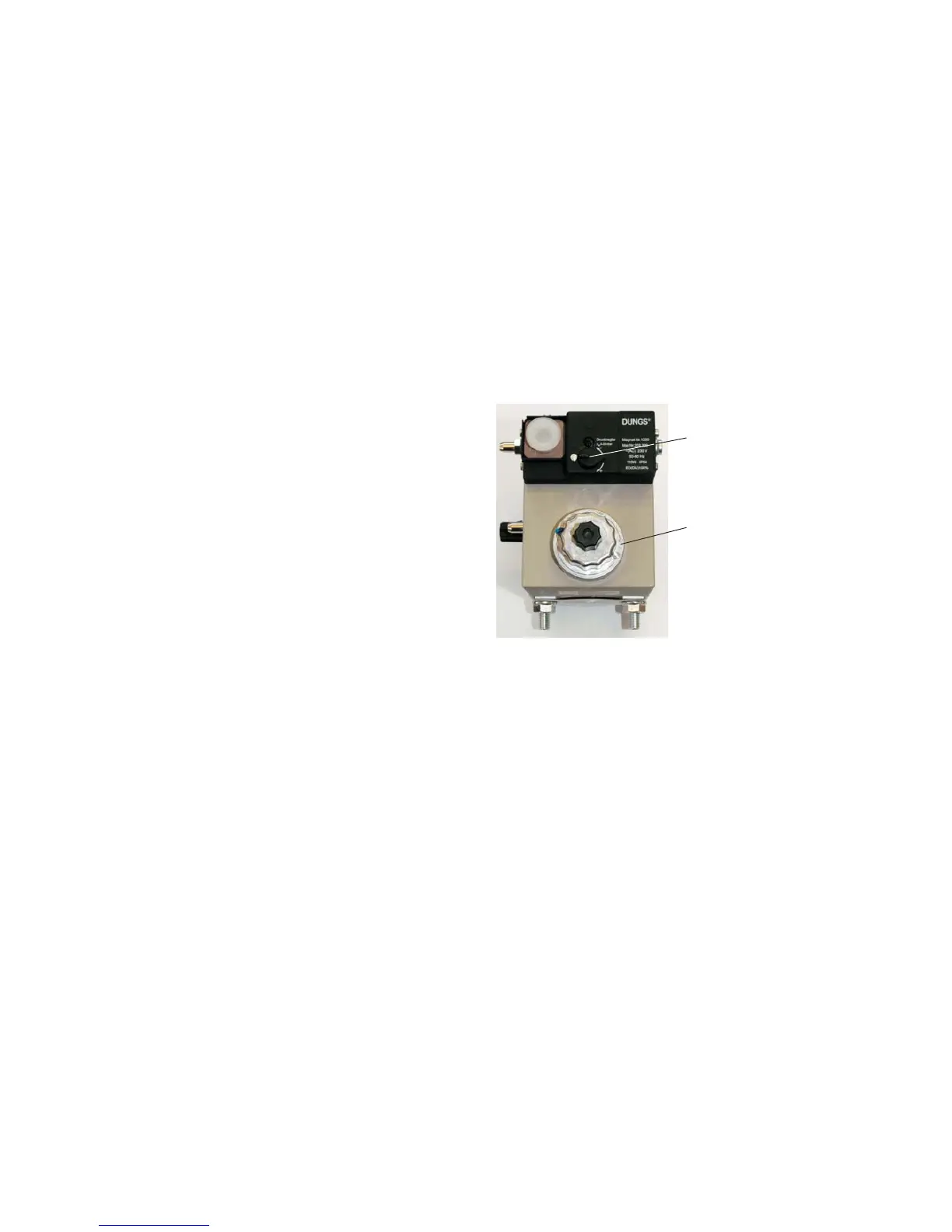
Pressure adjustment screw
under cover
Main volume regulator
13
Fig 2 Dungs Valves
pressure adjustment
 Loading...