15
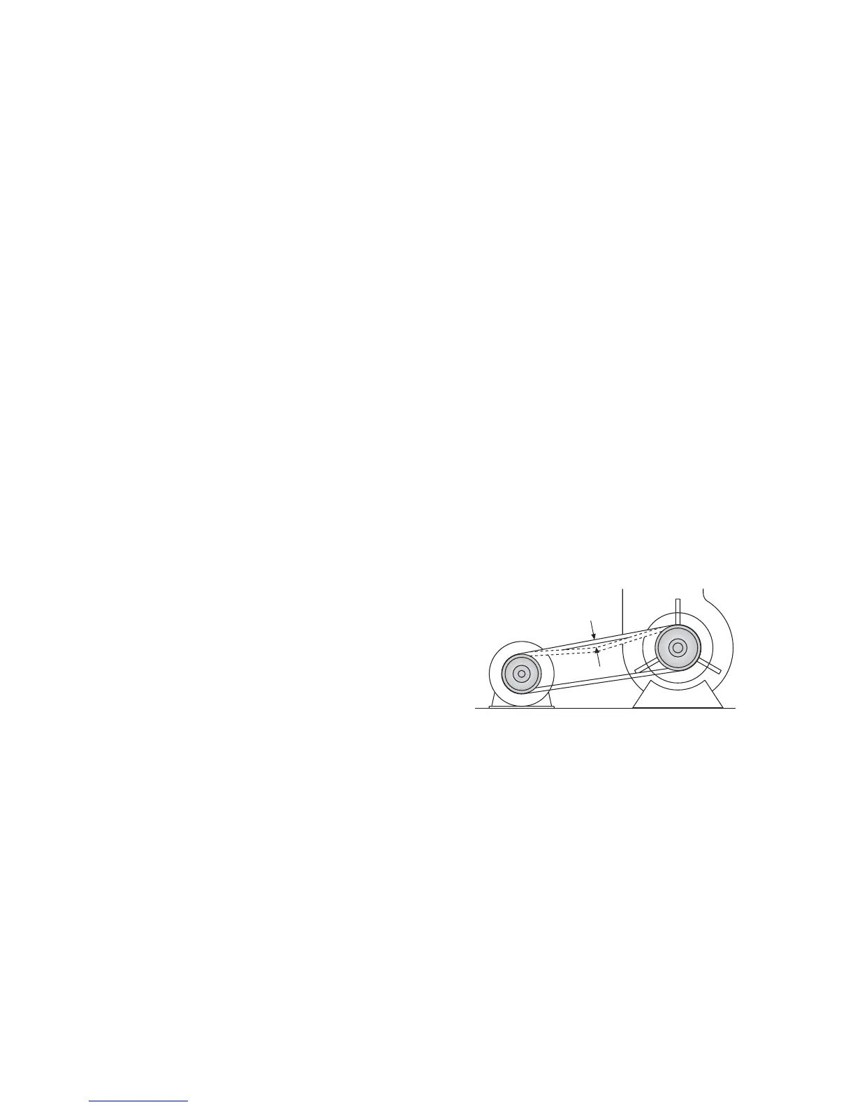
Fig 3 Fan belt
tension setting
6. Servicing
WARNING: Always switch off and disconnect electricity supply,
close the gas service valve or turn off the oil supply before
carrying out any servicing work or replacement of failed
components.
6.1 General
Full maintenance should be undertaken not less than once per
year. After any servicing work has been complete or any
component replaced the air heater(s) must be fully commissioned
and tested for fuel tightness as described in Section 5.
6.2 Burner Servicing/Maintenance
1. Refer to the burner instructions supplied with the heater and
complete the servicing/maintenance instructions therein.
Note: In the case of gas burners ignore any references in the
burner supplement to the gas controls assembly.
6.3 Heat Exchanger Cleaning
1. Remove the fan/limit thermostat(s) as described in 6.6.4 and
then remove the upper front panel of the heater to expose the
heat exchanger clean out panel. Remove the bolts securing the
panel, pull the panel forwards at the bottom and then lift up to
disengage from the heat exchanger and remove.
2. Withdraw the heat exchanger baffles.
3. Brush through heat exchanger tubes and remove loose material
using a vacuum cleaner.
4. If it is necessary to also gain access to the combustion chamber
disconnect the fuel and electrical connections from the burner.
Remove the nuts securing the burner to the heater and withdraw
the burner from the burner tube.
5. Reassemble all components in reverse order. Note: The
ceramic fibre gasket around the inside of the heat exchanger
clean out panel must be renewed. If the burner has been removed
the burner gasket should be replaced if necessary.
6.4 Fan Assembly
1. Remove the lower panels of the heater to gain access to the
fan section.
2. Inspect the fan blades to see that they are not damaged and
that there is no excessive build up of deposits that could give
rise to an imbalance. If necessary clean the fan blades using a
stiff brush and vacuum cleaner.
3. Replace panels accordingly.
6.5 Oil Filter (if applicable)
1. Release the securing bolt, or unscrew the filter bowl, to access
the filter.
2. Clean the filter or replace as deemed necessary.
3. Refit bowl ensuring that seals are correctly in place.
6.6 Replacement of Faulty Components
6.6.1 Burner Components
1. Refer to the burner instructions supplied with the heater for
information regarding replacement of components within the
burner.
6.6.2 Gas Controls Assembly (if applicable)
1. Remove the electrical connections from the gas control block.
2. Release the nuts securing the inlet and outlet flanges to the
gas control block and lift out the gas control block. Fit the
replacement assembly in reverse order ensuring the valve is
correctly orientated for the direction of gas flow.
6.6.3 Main Air Fan and Motor
Important: On 3ph heaters fitted with 3ph main fan motors
ensure that the fan direction of rotation corresponds with the
direction of rotation arrow on the fan guard or case. If necessary
reverse the direction of rotation by interchanging any two of
the motor live leads at the terminal strip in the electrical panel.
Should it be necessary to remove one or more of the fans for
cleaning proceed as follows.
6.6.3.1. CP 100 - CP 400
Note: These heaters are fitted with direct drive fan units.
1. Disconnect the fan motor electrical leads from the terminal
strip (Refer to wiring diagram supplied with the heater)
2. Remove the two screws, one on each side of the fan mounting
flange, that secure the fan to the fan shroud.
3. Remove the screws securing the heat exchanger mounting
frame to the fan shroud on the side that the fan is going to be
withdrawn.
4. Withdraw the fan from the slide rails.
5. Reassemble in reverse order.
6.6.3.2. CP 500 - CP 2000
Note: These units are fitted with belt driven main air fans.
1.Remove the lower side panels.
2. Release the motor mounting plate securing screws and then
remove the belt tension by turning the tension adjustment screw
anticlockwise. Remove the fan belts.
3. Remove the screws securing the fan mounting feet to the
heater framework and remove the fan. It may be necessary to
re-orientate the fan within the fan compartment and also to
release the fan shroud fixings in order to pass the fan through
the heater frame. On units with twin or triple fan sets on a
common fan shaft it will be necessary to first remove the fan
shaft.
4. Inspect the fan belts and if necessary replace with new.
5. Replace components in reverse order.
6. Do not over tension the fan belts. There should be
approximately 15mm of deflection when downward pressure
is applied to the belt(s) halfway between the motor and fan
pulleys.
12mm - 15mm
6.6.4 Fan and Limit Thermostats
6.6.4.1 CP 100 - CP 1000 - Fan / Limit Thermostat
- Honeywell L4064N
1. Release the single screw securing the fan and limit thermostat
cover and remove cover by pulling forward.
2. Release wiring from clamp terminals by pushing a small
screwdriver into the clamp release holes adjacent to the clamps.
3. Remove the 2 screws securing the thermostat to the heater
panel and withdraw thermostat.
4. Reassemble new unit in reverse order referring to the heater
wiring diagram to ensure correct wiring location.
Important: A replacement fan/limit thermostat will have a
brass link between the bottom fan terminal and the bottom limit
terminal (situated in the slot between the two terminals). This
MUST be removed, by breaking the link off using a pair of thin
nose pliers, before the replacement thermostat is installed.
5. Ensure that the fan and limit settings are as follows:-
Fan ON - 50°C, Fan OFF - 30°C
Limit CP 100 - 150 90°C
CP 200 - 800, 1000 110°C
CP 300 - 700 100°C
 Loading...