HEMNVx HEMSL A CRS ØD
10-3 n/a 120 91
15-4 n/a 120 91
18-5 n/a 120 91
25-5 n/a 142 112
30-6 30-6 142 112
40-8 n/a 142 112
n/a 45-9 142 112
50-6 50-6 142 112
60-7 n/a 220 142
n/a 60-12 220 142
75-9 75-9 220 142
A CRS
ØD
ØD
Silicone
Seals
Simulated enclosure
A CRS
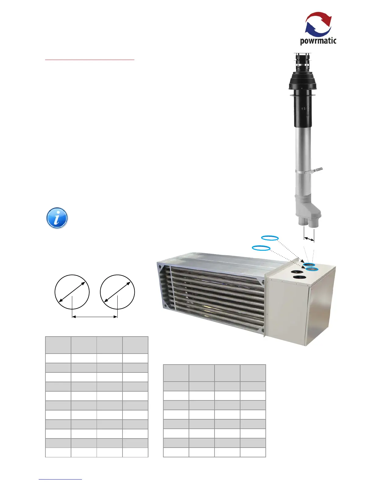
2.1.4.2 Type C Flued Installations
For vertical type C ued installations a vertical concentric
ue system should be used.
Nominal ue diameters are either 80mm, 100mm or
130mm dependent on heater size (refer to duties section
on page 6)
The maximum permitted length of ue system is 9m, If
an oset is required two sets of 45° bends should be used
each set being equivalent to 0.5m of ue length. 90° bends
may be used but each set will be equivalent to 1.0m of ue
length.
Exhaust ue outlet positions are shown in the previous
diagrams and tables.
Air inlet holes should be cut to the dimensions in the
following table to accept the silicone seals supplied.
(where ØD is the actual cut size in the casing/sheet metal).
The silicone seals supplied are not water tight
and should not be used in external vertical
applications. A suitable water tight seal or
sealant must be used in these instances.
HEMNVx HEMSL A CRS ØD
n/a 75-15 220 142
n/a 90-18 220 142
100-12 100-12 220 142
110-13 n/a 220 142
125-15 125-15 220 142
150-18 150-18 220 142
175-21 175-21 220 142
200-24 200-24 220 142
Type C Flue and air inlet cut hole sizes
and centres distances.
(refer to table below)
 Loading...