page no. 41 of 68
LX Range Users, Installation & Servicing Instructions Doc Ref M110 issue 1.0 Dec 2020.
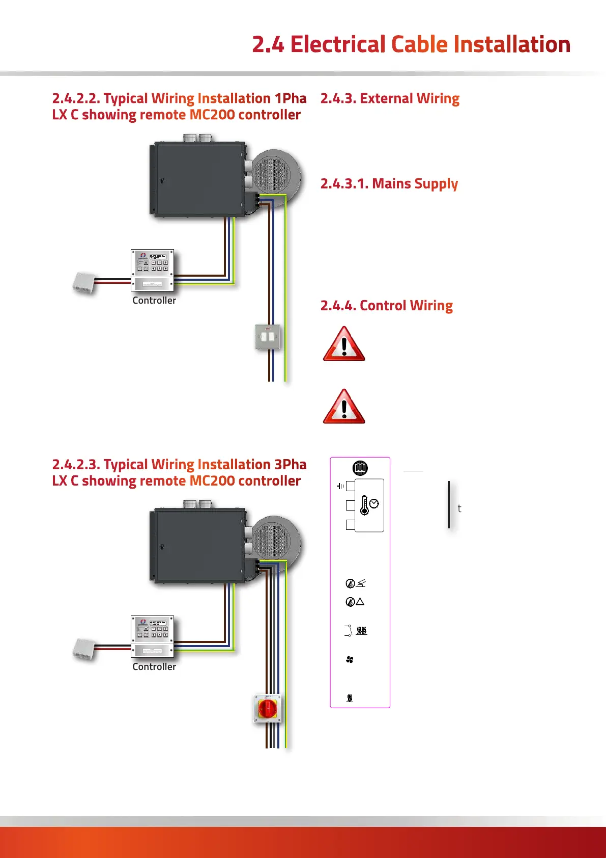
2.4 Electrical Cable Installation
2.4.2.2. Typical Wiring Installation 1Pha
LX C showing remote MC200 controller
Remote Sensor
(optional)
Controller
(MC200 shown)
Fused
Isolator
230V
Supply
2.4.2.3. Typical Wiring Installation 3Pha
LX C showing remote MC200 controller
Remote Sensor
(optional)
Controller
(MC200 shown)
Fused
Isolator
415V
Supply
2.4.3. External Wiring
The wiring terminals are located on the electrical panel
behind the side door of the heater which firstly has to be
opened.
2.4.3.1. Mains Supply
Mains input of either 230V 50Hz 1Ph or 415V 50Hz 3Ph
supply connections are via a separate terminal block.
Single phase mains supply range of 195V to 253V for a
nominal voltage of 230V AC. For input power refer to
following table. Control circuitry / external control mains
connections are via a numbered terminal strip.
2.4.4. Control Wiring
Warning: External controls MUST be
powered via heater terminal 10, 11 and
Earth
Warning: Ensure AC enable circuits (Fan
Only, Low Fire, High Fire etc.) are volt free
i.e. 0V (off) or 230V (on), as voltages >80VAC
may cause nuisance triggers.
New DrawingJMC 25.11.20
1
This drawing is copyright and the property of POWRMATIC LIMITED. It must not be used without
their knowledge, nor communicated to any other person or company.
MODIFICATIONDRN DATE ISSUE
TITLE:
Label Set: 143891102/LX
for Lx Control Panel
DRG NO:
S01GBE0368
Material:
Adhesive:
Finishing:
Colours: 1 x colour Black
OPP Gloss White PP (Digi)
PermPF-1
Finished in Rolls of 250, 1 Across,
Perforation between each label
Labels wound out. Right side off first
Laminate: Gloss Clear PP
Cut lines shown in magenta
!
1
2
3
4
5
6
7
8
9
1
0
1
1
0-10V
0V
L
N
E
i
ii
i
1
6
1
7
1
8
1
9
2
0
2
1
2
2
2
3
2
4
2
5
2
6
2
7
Exh Fan 0V
Black
Lim Stat2
Black
Lim Stat2
Grey
Lim Stat2
Brown
(Stat2) & Fan - E
Grn/Yel
Fan - L
Brown
Exh Fan - N
Blue
Fan - N
Blue
Exh Fan - E
Grn/Yel
Exh Fan Tacho
White
Exh Fan PCM
Green
Exh Fan - L
Brown
R
e
m
o
v
e
lin
k
to
c
o
n
n
e
c
t S
ta
t2
1
3
1
4
1
5
N
L
2
3
0
V
5
0
H
z
1
~
F
U
S
E
:
6
A
T
y
p
e
T
P/N: 143891102/LX
31
1
3
0
31
1
2
0
4
5
3
0
10
x
10
10
x
10
2
2
.5
10
15
LABEL DETAILS
Dimensions in
mm
New Programmer Icon (Terminals 10-12)JMC 21.12.20
2
Key:
Earth
Neutral
Live
OV (common)
0-10V d.c. Modulation signal
Burner Lockout Reset
Burner Lockout Indication
*High Fire Input
*High Fire Output
Fan Only
*Low Fire Input
230V Output
to controller
* ONLY WHEN USED
Heater terminal connections
Key:
Heater Mains Supply = 2 core and earth
MC200 Controller = 5 core and earth
= 2 core ELV (0-10Vdc)
alt. MC300 Controller = 7 core screened + LNE
Optional MC200 sensor = Screened 2 core*
* (screen must be grounded only at the MC200, See
instructions supplied with controller for wiring sizing,
Max. 100m)
Key:
Heater Mains Supply = 4 core and earth
MC200 Controller = 5 core and earth
= 2 core ELV (0-10Vdc)
alt. MC300 Controller = 7 core screened + LNE
Optional MC200 sensor = Screened 2 core*
* (screen must be grounded only at the MC200, See
instructions supplied with controller for wiring sizing,
Max. 100m)

 Loading...


