Chapter 4 Main circuit and terminal wiring
10
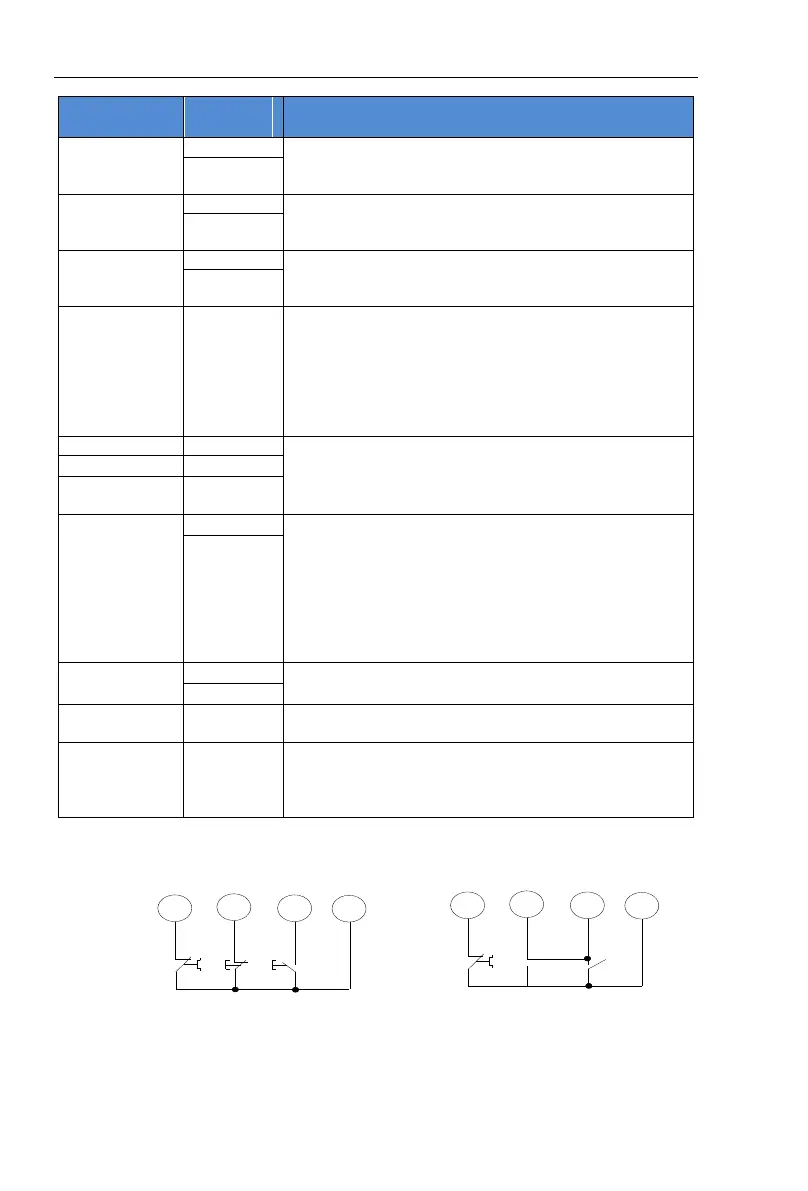
7
8
9
10
Transient
stop
stop
start
common
3lines way
7
8
9
10
Transient
stop
stop
start
common
2lines way:close K start
open K stop
K
Used to control bypass contactors, for the constant opening
of passive contacts, closed when the start is successful. The
contact capacity is: AC250V/5A.
The output mode and function are set by the setting item PE
and are often open passive contacts. The contact capacity is:
AC250V/5A.
The soft starter is closed when it fails or loses power, and it
is open when it is working properly. It is an passive contact.
The contact capacity is: AC250V/5A.
When the soft starter is working properly, this Terminal
must be short-connected to terminal 10. If this terminal and
terminal 10 are open, the soft starter stops working
unconditionally and is in failsafe state. This terminal can be
controlled by the normally closed output point of the
external protection device. When setting item PA to
0(Primary protection), this terminal function is disabled.
The terminals 8, 9, and 10 are external control start and stop
buttons input junction terminals. There are two ways to
connect, that is, 3 lines and 2 lines. Connections can be
selected as needed, as shown in Figure 4.3.
Terminal 11 and 12 are 0 to 20 ma, 4 to 20 ma DC analog
output: For real-time monitoring of motor current, at a full
degree of 20 ma, indicating that the motor current is 4 times
the nominal current of the soft starter. Externally observed
with 0 to 20 ma, 4 to 20 ma DC current meters, the
maximum output load resistance is 300 Ω. (Note: The
machine defaults to 4 to 20 ma output. If 0 to 20 ma output
is required, please explain it at the time of ordering. )
13 is the communication terminal "485-'' and 14 is the
communication terminal" 485 + ".
Control board
select jumper
The fan is always running when 2-3 is short, and the fan is
running when 1-2 is short(Default).
Control board
select jumper
Switching between online and bypass operations is
controlled by jumper J12, 2-3 short connections are
online(Default), and 1-2 short connections are bypass
operations.
(Note: Do not misconnect the external terminal line, otherwise it may cause damage to the
soft starter.)
Figure 4- 3
The main circuit and secondary wiring diagram of PR5300 series soft starter are shown in
Figure 4.4 below.
Soft starter terminals R, S and T are connected with three-phase power supply, and soft starter
terminals U, V and W are connected with motor.
 Loading...