6 A-MIMO-0003-V2_PCL
Introduction
4
This User Guide provides information on the installation
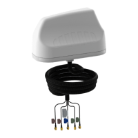
instructions of the MIMO-3-V2 antenna.
Threaded Spigot Mounting
Download the 1:1 drill template from
http://www.poynting.tech/downloads
• Choose the mounting location carefully and a
position at least 50cm from heat sources, with a
clear line of sight to the sky. It is recommended
that the antenna be installed at the highest
possible location on the vehicle’s roof so that
a signal can be received in a 360° radius, clear
of obstacles including parts of the vehicle’s
body and that the mounting surface is as at
as possible. The selected location must have
a conductive metallic surface area which is a
minimum of ±400x400mm to achieve optimal
performance.
• Once you have decided on the location and
checked that there are no obstructions such as
cables or channels below the mounting surface,
for the fastening nut and cables to pass through,
use the downloaded 1:1 drill template to mark
the mounting location.
• To prevent the marking tool or drill sliding off
course, use masking tape over the drilling point
to help hold the drill point in place. The masking
tape also prevents hot shavings from the drill or
hole saw which could penetrate and damage
the painted surface.
• Set the drilling machine to low speed and
carefully drill a pilot hole (Ø3mm drilling bit works
well). Use a Ø22mm metal hole saw or step drill to
open the hole to the required size.
Note: The recommended drill hole diameter for
MIMO-3-V2 is Ø22mm
• Clean the entire surface on which you plan to
mount the antenna. Cleaning is done so as not to
damage the vehicle’s paint and to ensure good
contact of the foam surface to the mounting
Installation Instructions
5