Do you have a question about the Poynting RIPPLE and is the answer not in the manual?
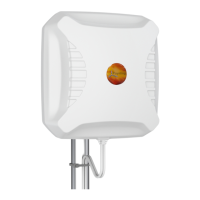
The Poynting RIPPLE is a high-performance LTE, 4G, and 5G antenna system designed for router manufacturers, providing a platform for high-speed internet and reliable connections, particularly in "near-shore" telecommunications tower environments. This system is engineered to facilitate robust connectivity for vessels, ensuring optimal signal reception and transmission.
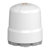
The RIPPLE antenna system comprises a cluster of ultra-wideband, omni-directional antennas. Its primary function is to provide a near-perfect 360° radiation pattern, enabling effective transmission and reception of radio signals across a wide frequency range. The system supports both vertically and horizontally polarized antennas, which is crucial for maintaining stable connections in dynamic environments like those experienced on a vessel. By integrating with routers, the RIPPLE acts as an external antenna platform, enhancing the router's ability to communicate with shore-based telecommunication towers. The design aims to minimize signal degradation caused by surrounding structures on a vessel, ensuring consistent high-speed internet access.
The RIPPLE is designed to operate across a broad frequency range, from 617 MHz to 6000 MHz, making it compatible with various LTE, 4G, and 5G cellular bands. This wide bandwidth ensures versatility and future-proofing for evolving telecommunication standards. The antenna system features an excellent horizontal (azimuth) radiation pattern, providing 360° coverage. This is vital for maintaining connectivity regardless of the vessel's orientation relative to the shore towers. The vertical (elevation) radiation pattern offers an approximate beamwidth of 60° at lower frequencies, meaning it can effectively cover 30° below and 30° above the horizon. This "vertical aperture" is critical for counteracting the effects of a vessel's pitch and roll, which could otherwise lead to signal loss. The system is designed to accommodate various router configurations. For instance, the A-RIPL-0016-V1-01 structure supports 4 x (4x4) routers with 8x Vertical Dipoles and 8x Horizontal Dipoles. The A-RIPL-0008-V1-01 structure supports 2 x (4x4) routers with 4x Vertical Dipoles and 4x Horizontal Dipoles. Both models can integrate GPS and Wi-Fi antennas, with specific configurations detailed for each. For example, the GPS antennas are typically vertical at 0° and horizontal at 180°, while Wi-Fi antennas are configured with horizontal and vertical polarizations at various angles (e.g., W1 Horizontal 22.5°, W2 Vertical 112.5°, W3 Horizontal 202.5°, W4 Vertical 292.5°). The physical dimensions of the RIPPLE are approximately 449.0 mm in diameter at the base, with a height ranging from 464.5 mm to 529.1 mm. The mounting holes are spaced 228.6 mm (9 inches) apart, with a diameter of 6.8 mm. The system also includes M12 x 1.75mm threads for mounting, with a depth of 45mm. The recommended router bracket mounts are designed to fit specific router dimensions:
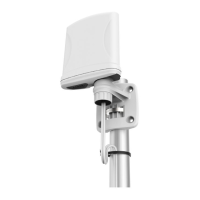
The RIPPLE is designed for ease of integration and robust performance in maritime environments. Installation Site Selection: The ideal installation site should minimize obstacles in the line-of-sight to shore-based towers. It is recommended to mount the antenna high enough to reduce the effects of surrounding structures like masts, exhaust funnels, and other antennas. Proximity to RADAR systems should be avoided, especially on the same horizontal plane, to prevent negative effects on the Signal-to-Noise Ratio (SNR) of the routers. A minimum separation of 4 feet (1.2 m) above or below the RADAR antenna level and 15 feet (4.6 m) away from high-power short-wave radars is advised. Rigid Mounting: The mounting platform must be rigid and free from excessive vibration. Installing the antenna at the center of the vessel can help minimize movement. Cable Management: The system provides clear guidelines for routing Ethernet and power cables through compression glands, ensuring adequate slack and protection against chafing and moisture. Grounding and RF Protection: All metal parts of the RIPPLE should be grounded to the bare metal of the vessel. This is achieved by attaching a ground wire/cable from the upper base plate ground point to a ground stud on the mounting mast near the base of the radome. Preservation of the bare metal contact point is crucial to prevent loss of ground due to rust and/or corrosion. The entire mounting to the hull should be permanently bonded and grounded. Router Integration: The RIPPLE is designed as an antenna system platform for routers. The internal structure allows for secure mounting of routers using specific brackets, and clear connector layouts facilitate proper RF, Ethernet, and power cable connections.
The warranty covers manufacturing defects in material and workmanship, provided the product was installed by professional personnel in compliance with the User Manual. The warranty does not cover defects caused by:
The RIPPLE system is a robust and versatile solution for enhancing cellular connectivity on vessels, offering a comprehensive platform for integrating high-performance routers and ensuring reliable communication in challenging maritime conditions.