RIPPLE SYSTEM INTEGRATION
1. BEFORE THE INSTALLATION
1.1. SELECTING THE ANTENNA INSTALLATION SITE
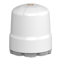
The RIPPLE consists of a cluster of ultra-wideband, omni-directional antennas, which
provides a near-perfect 360° radiation pattern. A ‘Radiation Pattern’ defines an antenna's
ability to effectively transmit or receive radio signals within the three-dimensional area. The
measured radiation patterns of the RIPPLE are provided in the technical document.
An ideal vertical polarised, omni-directional antenna will have a 360° radiation pattern on the
horizon. While an ideal horizontal polarised, omni-directional antenna will have a 360°
radiation pattern perpendicular to the horizon. The RIPPLE antenna system offers a
combination of vertically and horizontally polarised antennas. This implies that the
installation site of the antenna should have limited obstacles in the line-of-sight of the
antenna system.
Any substantial structure between the shore-based towers and the RIPPLE will cause
degradation of the signal. Therefore, the installation site of the RIPPLE should be chosen
accordingly to minimize blockage caused by the structures on the vessel.
It is advised that the RIPPLE antenna system be mounted high enough to minimize the
effects of surrounding structures. Large, solid, structures will cause significant signal loss
while wire rope stays, lifelines, small-diameter handrails, and other accessories may cause
little to no noticeable loss.
Horizontal Radiation Pattern (or Azimuth) - The RIPPLE
has an excellent horizontal, also
known as ‘Azimuth’ radiation pattern that will ensure near-perfect reception from 360°
around the vessel, provided that the area ‘around’ the Antenna System is clear of obstacles.
Vertical Radiation Pattern (or Elevation) – The RIPPLE also has an excellent vertical radiation
pattern, also known as the ‘Elevation’ radiation pattern. The RIPPLE has an approximate
vertical beamwidth of 60° at the lower frequencies, which means 30° below the ‘horizon’ and
30° above the ‘horizon’. Where the ‘horizon’ is the 0° ‘line-of-sight’ of the antenna pointing
on the horizon. The antenna elevation should be unobstructed as far as possible.
This ‘vertical aperture’ is important to counteract any ‘Pitch-and Roll’ of the vessel that would
result in loss of transmission- or reception of the signal.
Obstacles - Most metal structures potentially attenuate (degrade) the radio signal that is
being transmitted from or received by the RIPPLE. Examples of solid objects are masts,
exhaust funnels, other antennas, etc.
Close proximity to RADAR - Do not install the antenna near the Vessel’s RADAR, especially
on the same horizontal plane. The electromagnetic energy from the RADAR may negatively
affect the Signal-to-Noise Ratio (SNR) of the routers installed in the RIPPLE.