7. CONNECTOR LAYOUT INSIDE THE ANTENNA
7.1. ANTENNA CONFIGURATION
The verticals (V) are the medium to high gain OMNI antennas. The horizontals (H) are the
low-gain OMNI antennas.
Step 1.
Please study the following pictures to decide how to do cable management for routers
installed.
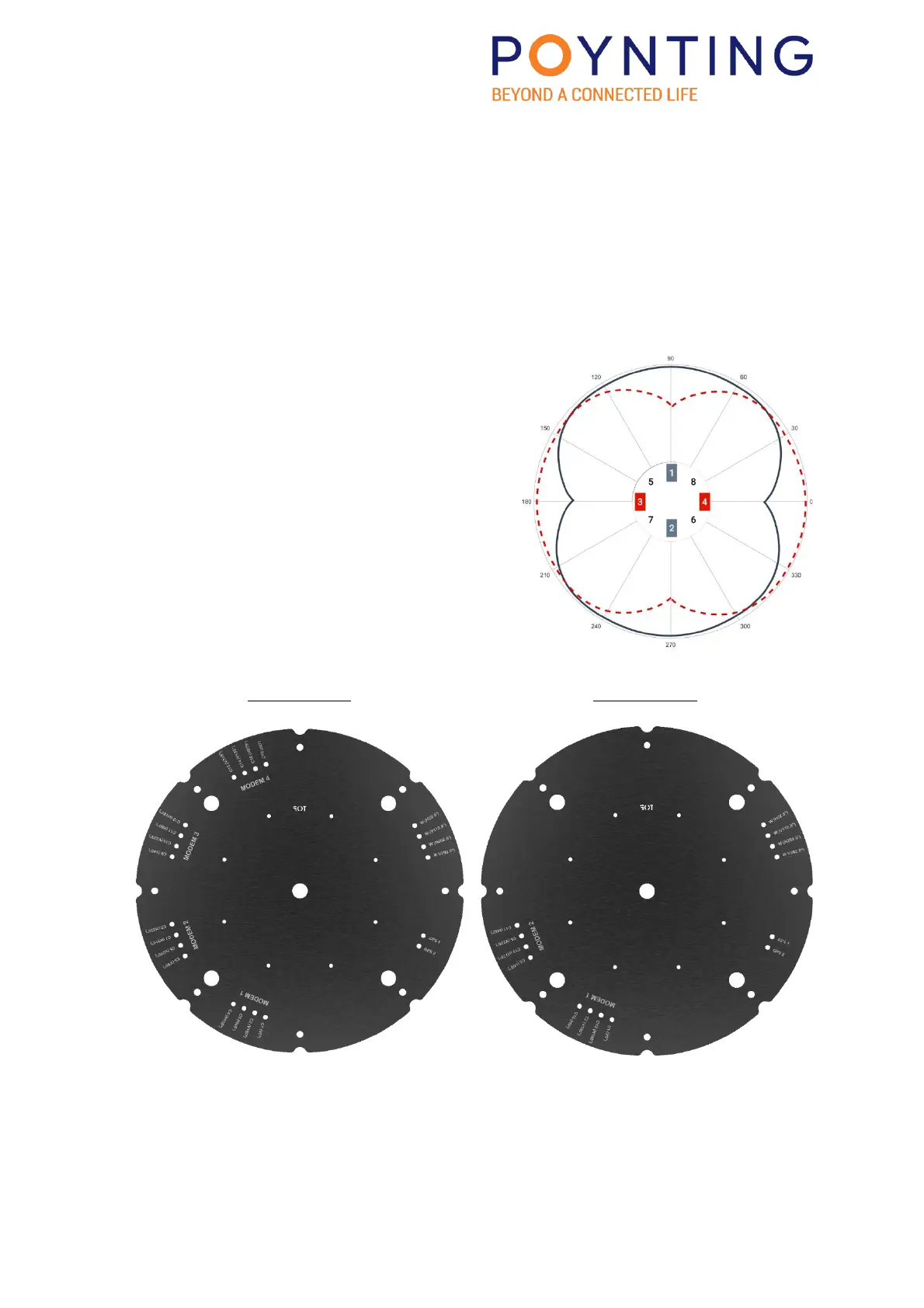
1. RIPPLE-0016 Configuration: This configuration
connects 4 x (4x4) Routers (see Page 16) to
• 8x Vertical Dipoles
• 8x Horizontal Dipoles.
2. RIPPLE-0008 Configuration: This configuration
connects 2 x (4x4) Routers (see Page 17) to
• 4x Vertical Dipoles
• 4x Horizontal Dipoles.
3. Attach Wi-Fi and GPS Antennas as per Diagram
(see Page 18)
RIPPLE-0016 RIPPLE-0008
See Pages 20 and 21 for detail.