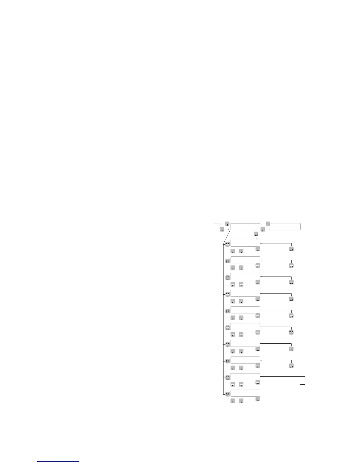
CapaC
SEns1t
nEt
dEad L
dspd1J
S1GnaL
CoUnts
opNodE
UpLoad
dnLoad
SET FUN
0
0
0
0
0
0
0
0
0
0
SET FUN
SET FUN
SET FUN
SET FUN
SET FUN
SET FUN
SET FUN
SET FUN
SET FUN
SET
FUN
PRG
Enter Value
PRG
PRG
Enter Value
PRG
PRG
Enter Value
PRG
PRG
Enter Value
PRG
PRG
Select Value
PRG
PRG
Read Value
PRG
Read Value
PRG
Select Value
PRG
PRG
PRG
Transmit setup data
to serial port
0
0
Receive setup data
from serial port
CONFIGURATION PARAMETERS
Through the setting of the parameters listed below, the theoretical Full Scale DAT 400 calibration is
performed. These steps with the zero calibration described on the next page must be completed. The
procedure ensures a good accuracy of the system (maximum error <1% FS) if there are no mechanical
problems.
Program the known values of total capacity and sensitivity of the load cells and the approximate values
of net capacity and calibration. If the parameter SENSIT is not programmed, it is taken the 2.0000
mV/V value.
If the parameter CAPAC is programmed other than 0, according to the data CAPAC, SENSIT, NET and
DEAD L , the instrument automatically runs the following functions:
Resetting the linearization points.
Selection of the value of the division, however, to be modified, to the best of 10,000 divisions.
Calibration of the theoretical approximate calibration of the weight (zero and full scale).
Automatic programming of the overload setpoint (= NET).
These functions are performed each time you change one of the 4 parameters shown.
When you change the DSPDIV selection., it is automatically recalculated to full-scale calibration. The
selections are incompatible with the calibration parameters or calibration in memory are not accepted.
The selection programmed in Opmode is read from the instrument when it is switched on and it makes
that the instrument operates in that way.
CAPAC CAPACITY OF THE WEIGHING SYSTEM
It defines the value corresponding to the sum of the rated capacity
of the load cells. In the case of systems with only one load cell and
“N” fixed supports, enter the capacity value of the cell for the total
number of supports. This figure represents the full scale value of the
weighing system.
Following the change of the parameter value, the theoretical tare of
the weight is recalculated.
Values: from 1 to 500000
Unit: the same of that displayed
Default: 10000
sEnsit LOAD CELLS SENSITIVITY
Set the value corresponding to the average sensitivity of the load
cells, in mV / V. The instrument accepts values between 0.5 and 4
mV / V. If no value if programmed, it’s assumed it is 2mV/V.
Following the change of the sensitivity value, the theoretical tare of
the weight is recalculated.
Values: from 0.5000 to 4.0000 mV/V
Default: 2.0000