INPUTS
24 VDC
INPUT 1
INPUT 2
+
-
COM. INPUT
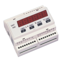
CONNECTIONS OF THE LOAD CELL/S
The cell/s cable must not be channeled with other cables, but must
follow its own path.
The instrument can be connected up to a maximum of 8 load cells
of 350 ohm in parallel. The supply voltage of the cells is 5 Vdc and
is protected by temporary short circuit.
The measuring range of the instrument involves the use of load cells
with a sensitivity of up to 3.5 mV / V.
The cable of the load cells must be connected to terminals 13-18.
In the case of 4-wire load cell cable, jumper the terminals 13 to 16
and 14 to 15.
Connect the cell cable shield to the terminal 9.
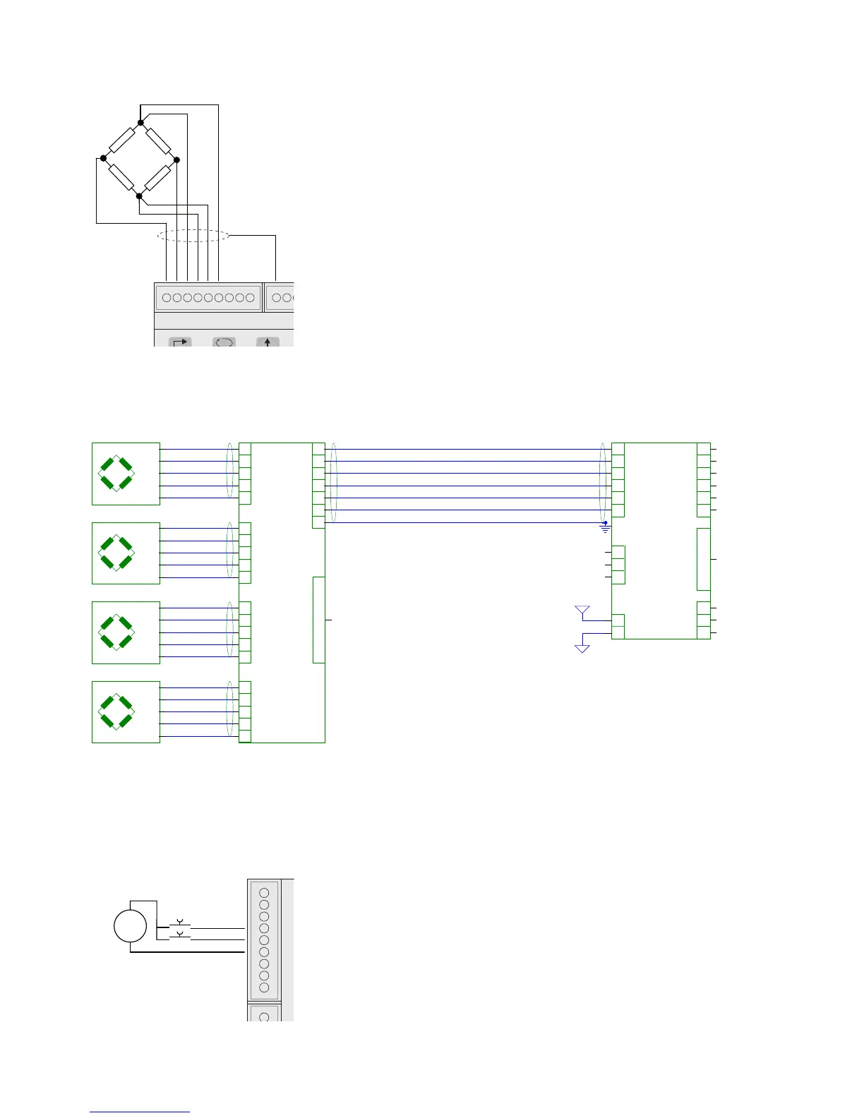
In the case of the usage of two or more load cells, use special junction
boxes (CEM4/C or CSG4/C). Below please find their connection.
LOGIC INPUTS
The two logic inputs are opto-isolated.
The cable connecting the logic input should not be channeled with
the power cables.
The function of the two inputs is as follows:
INPUT1 Resetting the displayed value (gross, net or peak)
INPUT 2 PRINT
The activation of the two functions is accomplished by bringing the
external power supply 24 Vdc to the corresponding terminals as
shown in the figure.