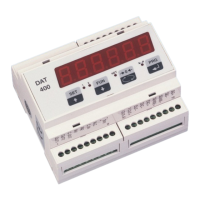
LOGIC OUTPUTS
The two opto-isolated relay outputs are the normally open contact.
The capacity of each contact is 24 Vdc, 100 mA max.
The cable connecting the outputs should not be channeled with the
power cables. The connection should be as short as possible.
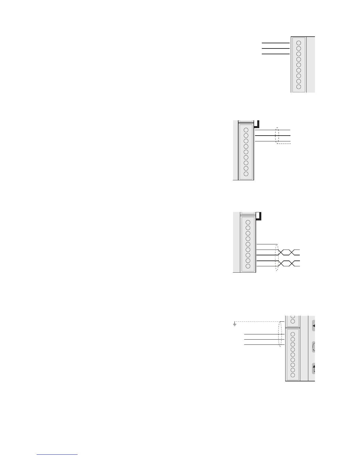
ANALOG OUTPUT (OPTIONAL)
The transmitter provides an analog output in current and voltage.
Analog voltage output: range from -10 to 10 V or -5 to 5 V, 10 KΩ
minimum load.
Analog current output: range from 0 to 20 mA or 4 to 20 mA. The
maximum load is 300 Ω.
To achieve the serial connection, use a suitable shielded cable,
making sure to connect the shield to one of the two ends: to pin
9 if connected on the side of the instrument, to the ground if it is
connected on the opposite side.
Attention: do not connect the analog output to devices that are
switched on.
RS485:
The serial port RS485 (2-wire) is present in the model DAT 400/
RS485.
To achieve the serial connection, use a suitable shielded cable,
making sure to connect the shield to one of the two ends: to pin
23 if connected on the side of the instrument, to the ground if it is
connected on the opposite side.
The cable should not be channeled with the power cables.
SERIAL COMMUNICATION
RS232:
The RS232 serial port is always present and handles various pro-
tocols.
To achieve the serial connection, use a shielded cable, making sure
to connect the shield to one of the two ends: to pin 25 if connected
on the side of the instrument, to the ground if it is connected on the
other side.
The cable must not be channeled with power cables; the maximum
length is 15 meters (EIA RS-232-C), beyond which you should take
the optional RS485 interface.