15
9 6
B_LINE
A_LINE
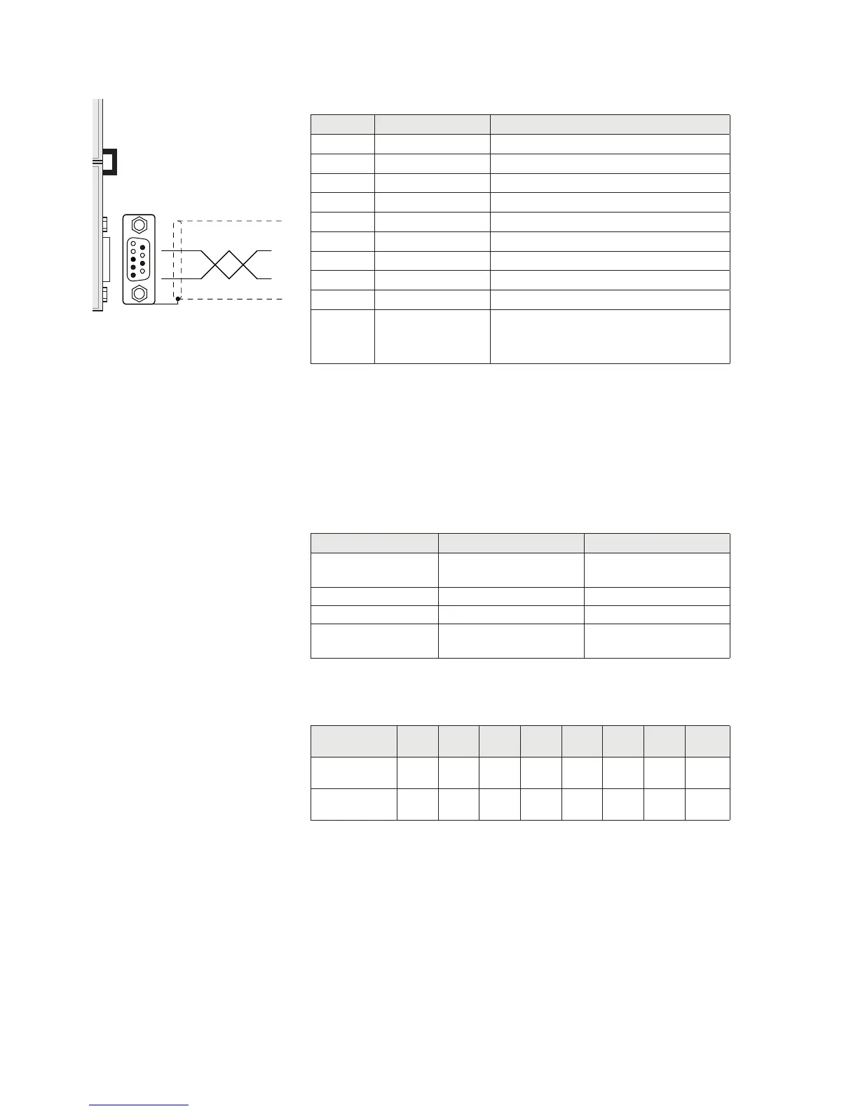
PROFIBUS DP CONNECTION (OPTIONAL)
Pin Signal Description
1 - -
2 - -
3 B line +RxD/+TxD, level RS485
4 RTS Request to send
5 GND Ground (isolated)
6 + 5V Bus Output +5V termination (isolated)
7 - -
8 A line -RxD/-TxD, level RS485
9 - -
Housing Cable shield Internally connected to protective
earth according to Profibus
specification
For connection to the Profibus Master, use a standard Profibus cable.
The typical impedance of the cable should be between 100 and
130 Ohms (f> 100 kHz). The cable capacity (measured between
conductor and conductor) should be less than 60 pF / m and the
minimum cable cross section should not be less than 0.22 mm2
In a Profibus-DP network, you can use either cable type A to type B
cable, depending on the required performance. The following table
summarizes the features of the cable to be used:
Specification Type A Cable Type B Cable
Impedance from 135 to 165 ohm
(f = 3 – 20 MHz)
from 100 to 300 ohm
(f > 100 kHz)
Capacity < 30 pF/m < 60 pF/m
Resistance < 110 ohm/km -
Conductor cross
section
> 0,34 mm
2
> 0,22 mm
2
The following table shows the maximum length of the wires line with
cable type A and type B, function of the different communication
speed required:
Baud rate
(kbit/s)
9.6 19.2 187.5 500 1500 3000 6000 12000
Cable A lenght
(m)
1200 1200 1000 400 200 100 100 100
Cable B lenght
(m)
1200 1200 600 200 - - - -
For a reliable operation of the Fieldbus, should be used a line ter-
mination at both ends.
In the case of multiple DAT 400 instruments, use the line termination
at only one instrument.
For configuring the instrument, the GSD file is available (hms_1810.
GSD) that must be installed in the master.