25PM-1440BV v3 2020-10 Copyright © 2020 Quality Machine Tools, LLC
Figure C Drill rod between
centers
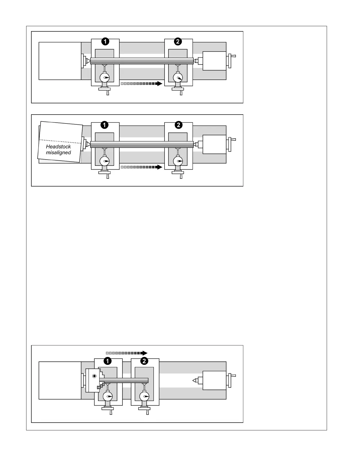
Figure D Misalignment of the
center turning
by as little as 0.002”, a tiny amount even if jacking screws are
provided. What this amounts to is that headstock adjustment
is a highly sensitive, iterative procedure that should not be
attempted casually. What follows is a general outline. Specic
instructions for the PM-1440BV follow this section.
HEADSTOCK ALIGNMENT METHODS
Method 1
Make a series of "cut-and-try" passes on scrap material. If the
workpiece is thinner at the tailstock end, the headstock needs
to be pivoted away from the tool, and vice versa.
Method 2
This uses the 3/4 or 1 inch ground drill rod described in "Pre-
cise method" above for center-to-center alignment.
Install the drill rod in a collet or independent 4-jaw chuck with
about 5 inches protruding, Figure E. Center drilling is not need-
ed.
1. Adjust the chuck for minimum runout at position (1).
2. Check the runout at (2). Pointer movement when traversing
is not a concern at this stage.
3. If the drill rod is perfectly aligned with the spindle axis, there
should be no dierence in TIR at (1) and (2).
4. If there is a signicant dierence in TIR* from (1) to (2), try
to correct this by loosening, then re-tightening the chuck/
collet, while levering the outer end of the rod (gentle tap-
ping with a non-marring hammer can also be helpful).
When the runout at (2) has been minimized, re-check at
(1), then repeat at (2), etc.
5. When (and only when) the TIR at both locations is the
same, or very close, can it be said that the rod is concentric
with the spindle.
6. Compare dial indications when traversing from (1) to (2).
Ideally, there will no change.
Figure E Perfect alignment:
zero indicator change be-
tween locations 1 and 2
* Factors that may aect runout
Straightness and roundness of the drill rod; Chuck installation
(check for cleanliness and tightness); "Pointing accuracy" of
the chuck (the gripping surfaces of chuck jaws may not be par-
allel with the axis of the chuck and spindle — especially likely
if the chuck is worn).

 Loading...

