26PM-1440BV v3 2020-10 Copyright © 2020 Quality Machine Tools, LLC
Figure F Morse taper test bar
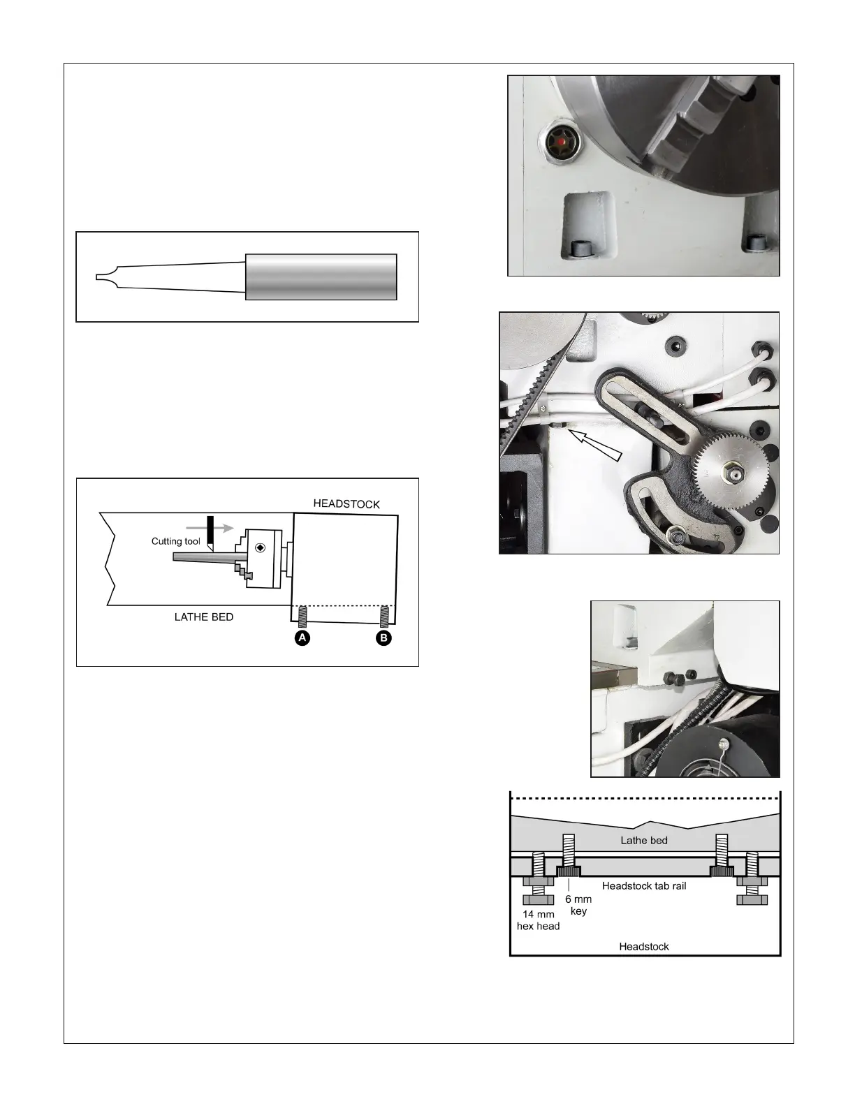
PM-1440BV HEADSTOCK ALIGNMENT
Figure A1 is an exaggerated top-down view of what happens
if the spindle is not precisely aligned with the lathe bed. This
is correctable by slightly loosening the attachment screws,
Figures A2 and A3, then adjusting the screws set into a tab rail
below the headstock, Figure A4.
CAUTION!
Correcting headstock misalignment is a multi-step process re-
quiring a number of extremely small adjustments, each one
followed by an alignment test, either cut-and-try, or one of the
other methods previously described.
A scarcely detectable rotation of an adjusting screw can
be the dierence between perfect alignment and unac-
ceptable taper. In other words, think in terms of thousandths
of an inch or less. Simply loosening the socket heads, Figure
A4, can be enough to correct a taper problem — or add to it in
the wrong direction.
Figure A3 Misaligned headstock
In this illustration the workpiece diameter increases as the cut-
ting tool moves toward the chuck. Correct this by screwing in
(A) a fraction of a turn to rotate the headstock counter clock-
wise, moving the workpiece away from the tool. Screw in (B)
if the taper is in the other direction, thinner toward the chuck.
Figure A4 Alignment adjustment screws
The socket head screws lock the adjustment by pulling the tab
rail toward the lathe bed. Loosen the inner socket head screws
a fraction before touching the hex head screws.
Figure A3 Headstock attachment screws, LH
One of two
Figure A2 Headstock attachment screws, RH
Method 3 - Morse Taper Test Bar
This is a catalog-only item available from many suppliers (de-
pending on the source it may be named dierently). The test
bar in Figure F has a tapered shank to t the spindle, and a
parallel portion several inches long. The diameter of the paral-
lel portion is unimportant. What matters more is its nish and
lack of taper— check before installing. Whatever taper there
may be can be allowed for in the alignment test, as Figure E.
Runout should be less than 0.0005" TIR.
 Loading...


