24
PM-727MV v6 2020-10
Copyright © 2020 Quality Machine Tools, LLC
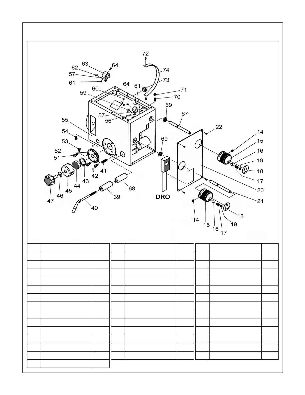
HEADSTOCK CASE COMPONENTS Fig 4
Ref Description Part
14 Screw: M6 x 8, set (2) Z5836
15 Gear shift knob (2) Z5837
16 Ball, 6.5 (2) Z5838
17 Compression spring (2) Z5839
18 Shift knob label (2) Z5840
19 Screw: M8 x 8, set (2) Z5841
20 Faceplate Z5842
21 Gear shift shaft 2-3-1 Z5843
22 Screw:M4x6 button hd Z5844
39 Quill lock (L) Z5845
40 Quill lock handle Z5846
41 Screw: M10 x 35, set Z5847
42 Roll pin 3 x 12 (2) Z5848
43 Retaining ring: 18, ext Z5849
Ref Description Part
44 Coil spring, quill return Z5850
45 Spring housing Z5851
46 Washer Z5852
47 Knob (M6) Z5853
51 Screw:M5x10 phil hd(3) Z5854
52 Spring ange Z5855
53 Screw:M5x10 at hd Z5856
54 Oil drain plug Z5857
55 Headstock casting Z5858
56 Gear shift crank H-L Z5859
57 Roll pin, 4 x 10 (2) Z5860
58 Screw: M6 x 10, set Z5861
59 Gear shift shoe, H-L Z5862
Ref Description Part
60 Screw: M6 x 8, set (2) Z5863
61 Nut, M6 hex (2) Z5864
62 Gear shift shoe, 2-3-1 Z5865
63 Gear shift crank 2-3-1 Z5866
64 Screw:M4x20 skt hd (2) Z5867
67 Gear shift shaft H-L Z5868
68 Quill lock (R) Z5869
69 Oil seal, 10 x 22 x 7 Z5870
70 Screw: M6 x 20, set Z5871
71 Nut, M6 hex Z5872
72 Rivet, 2.5 (2) Z5873
73 Oil sight glass Z5874
74 Angle scale Z5875
Missing numbers are either: (1) components not tted, or; (2) components shown in the Headstock Drive diagram
All dimensions in mm
There may be detail dierences
between this representative drawing
and the machine as supplied