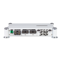
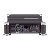
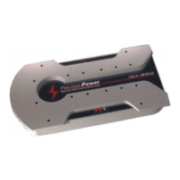
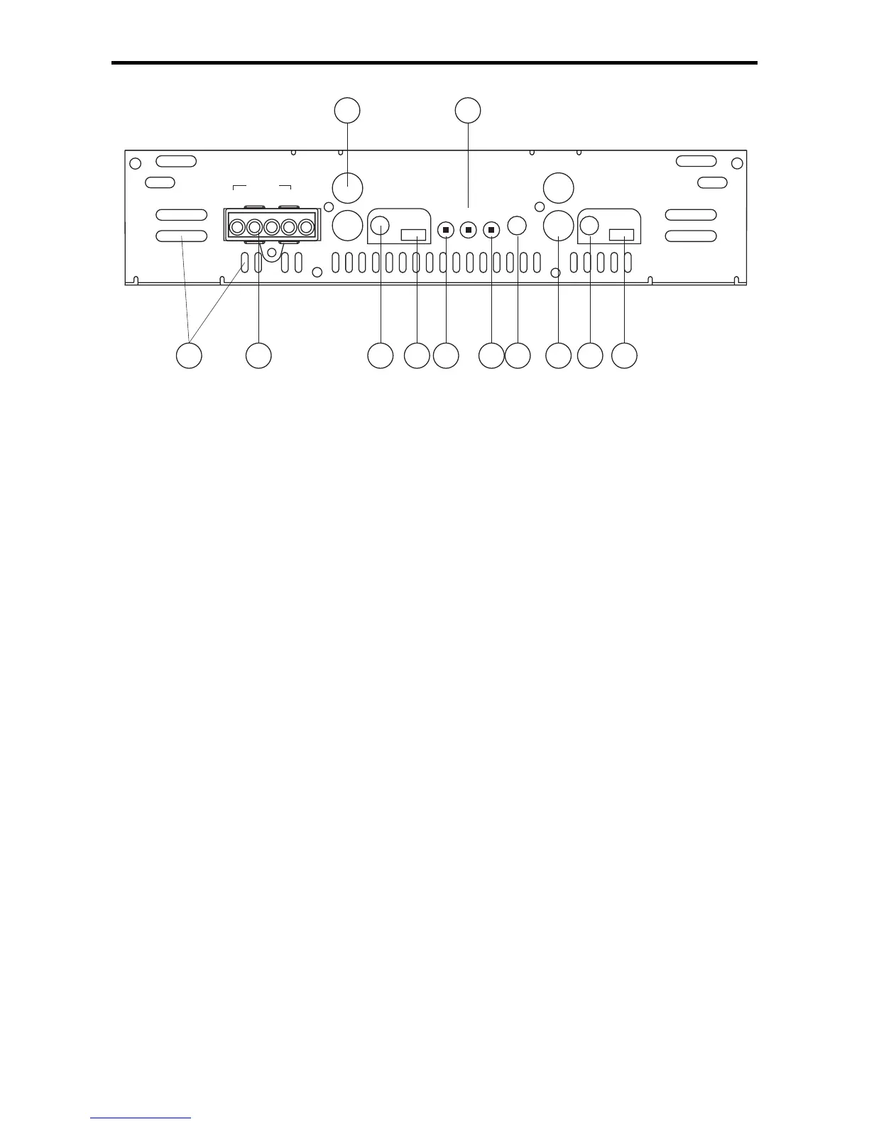
FRONT PLATE DIAGRAM
1. Cooling Plenums: Maintain a minimum 2” clearance around
cooling plenums for proper amplifier cooling.
2. Speaker/Remote Connector: The
PowerLock
TM
speaker
connector.
3. Output Xover Freq. Control: Use this control to adjust the sub
bass output signal crossover frequency from 30Hz to 4kHz. (See the
Crossover Frequency chart in this manual).
4. Output Xover FULL/LP/HP Switch: Select the desired crossover
setting HP/LP/FULL for the signal of the RCA outputs.
5. QBASS
TM
Freq.: Use this switch to set the
QBASS
TM
frequency
(applicable to model A800/2 and A1000/2, refer to
QBass
Plus/QBass Remote
section).
6.-12dB Input Attenuation: Push this switch ‘IN’ for high voltage
(4V-12V) capability. This button pushed ‘IN’ must be used for
speaker level input on common ground head-units or for high
voltage line drivers.
7. Gain: Use this control to match the output level of the source unit
to the amplifier.
8. Input: Plug in the RCA leads from your source here.
9. Xover Adjustment: Adjusts the crossover between 30Hz and 4kHz.
10. Xover FULL/LP/HP Switch: Select the desired crossover
setting FULL/LP/HP.
11. QBass: Use this switch to set the
QBASS
TM
frequency
(applicable to model A800/2 and A1000/2). On the A500/2 this is the