Page 15For technical questions, please call 1-888-866-5797.ITEM 62548
SAFETYSETUPOPERATIONMAINTENANCE
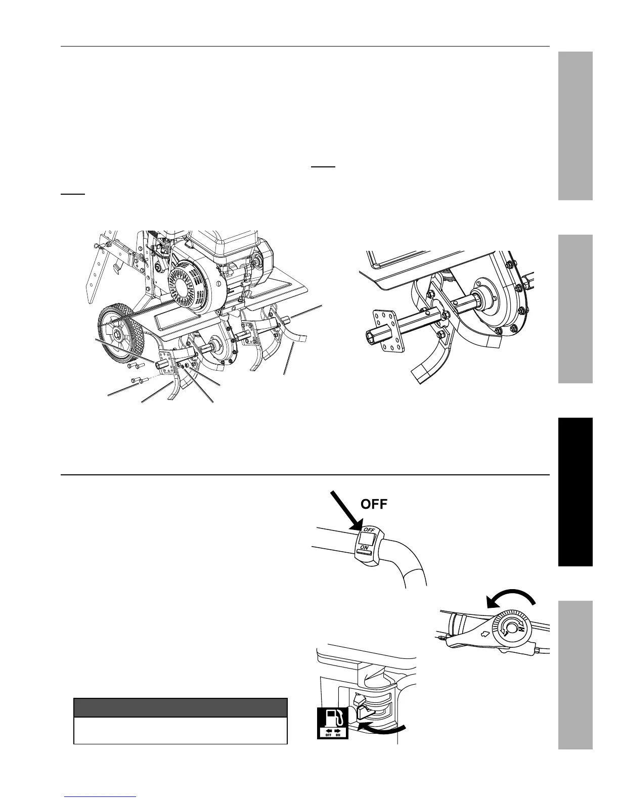
Narrow Width Tilling
The Tiller may be set up for narrow tilling by removing
the outer Tine Blades from each of the two Tine
Blade Assemblies using the following procedure:
a. Make sure the Engine Switch is in the “OFF”
position and disconnect the Spark Plug cap.
b. Loosen and remove four sets of Bolts (59), Spring
Washers (60), and Nuts (61) securing the outer
Tine Blades in place on the Tine Shaft of each
Tine Blade Assembly. Remove the Blades and
set aside with the hardware. Refer to Figure D.
Note: Examine Tine Blade positioning and
hardware alignment before removal to
make correct reattachment easier.
c. Make sure the outer Tine Blades
are removed from both Tine Blade
Assemblies before operating Tiller.
d. To return to normal width tilling replace the
outer Tine Blades onto both Tine Shafts.
When reattaching the Tine Blades make sure
the Blades and hardware are replaced in
the same orientation as when removed.
Note: When installed properly the cutting
edges of the Tine Blades will face forward.
Bolt
Nut
Spring WasherTine Blade
Tine Blade
Tine
Shaft
Tine
Shaft
Tine Blade Assembly with outer
Tine Blades removed from Tine Shaft.
Figure D
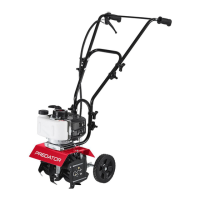
Stopping the Engine and Tiller
1. To stop the Engine in an emergency,
turn the Engine Switch off.
2. Under normal conditions, use the following procedure:
a. Release the Clutch Lever.
b. Rotate the Throttle Control
counterclockwise to the low position.
c. Turn the Engine Switch off.
d. Close the Fuel Valve.
e. Clean external parts with clean cloth, remove
debris from Tine Blades and Shaft, then
cover the equipment and store in a dry, level,
well-ventilated area out of reach of children.
NOTICE
See Long-Term Storage on page 21
for complete storage instructions.