EasyManua.ls Logo

Prestige APS-57 User Manual

Default Icon
19 pages
To Next Page IconTo Next Page
Page #1 background imageLoading...
Page #1 background image
128-7767
1 of 19
The selectable features can be set manually as explained below, or with the RF feature programmer.
To set features using the RF programmer, follow the instructions packaged with the programmer.
Factory default settings are indicated by bold text.
Note : The method of manual override can either be selected to operate from the valet switch or operate as custom code.
Be certain to place a check mark indicating the method used in the box located on the last page of the owner's manual.
NOTE: Keyless Entry Models with no horn output will Flash the Parking Lights instead of chirp where chirp is indicated.
Also, No data will be indicated if a feature is not available for a particular model. The unit will enter the feature but no selection will be available.
RF Programmable Feature Bank 1 Is For Transmitter Programming See Transmitter Programming Guide.
RF Programmable Features Bank 2 Is Alarm Selectable Features:
Feature Selection 1 Chirp 2 Chirps 3 Chirps 4 Chirps 5 Chirps 6 Chirps
1st DoorL/UL 1 Sec. 3.5 Sec. 1 Sec L, Dbl. U/L Dbl L, 1 Sec UL Dbl L, Dbl UL 1 S l/350mS ul
2nd Accy Lock Not Available
3rd Accy. UL Not Available
4th Headlights Not Available
5th Passive Locks Not Available
6th Pass/Act Arm Not Available
7th Siren/Horn Not Available
8th Horn Chirp Not Available
9th O/R Method Not Available
10th 2 Step U/L Not Available
11th Chp Del Tx Not Available
12th Voltage/Hd Wire Not Available
13th Trigger Circuits Not Available
14th Lock/Unlock Poll Not Available
15th Aux Ch 5 Sel Not Available
16th Aux Ch 6 Sel Not Available
17th Aux Ch 7 Sel Not Available
18th Trigger Delay Not Available
When using the RF programmer, enter the program mode as follows:
Turn the ignition on
Press and release valet switch 3 times
turn ignition off then on
Press and hold valet switch for 5 seconds
Siren and or lights chirp/flash 2 times indicating access to RF feature program mode.
Model APS-57
Installation Manual
1
Get other manuals https://www.bkmanuals.com
Question and Answer IconNeed help?

Do you have a question about the Prestige APS-57 and is the answer not in the manual?

Prestige APS-57 Specifications

General IconGeneral
Number of Buttons on Remotes4
Remote Start FunctionsYes
Keyless EntryYes
Number of Remotes Included2
Trunk ReleaseYes
Panic ModeYes
System TypeRemote Starter
Engine Immobilizer BypassYes (Requires additional module)

Summary

RF Programmable Features

Installation of Major Components

Control Module Installation

Guidelines for mounting the control module for optimal performance and safety.

Hood Pin Switch Installation

Procedure for installing the hood pin switch for safety shut down.

Push-Button LED Switch Installation

Instructions for mounting the push-button LED switch for valet functions.

Wiring the 6 Pin Main Power Harness

Wiring the 12 Pin Input/Output Harness

Specific Wire Output and Shutdown Connections

Brake Switch Positive Shutdown Wiring

Diagram and instructions for brake switch positive shutdown input.

Advanced Wiring and Bypass Functions

Shock Sensor Bypass Wiring

Wiring diagram for bypassing the shock sensor during remote start activation.

GM VATS Key Override Bypass

Procedure and diagram for bypassing the GM VATS system.

Tachometer Input and Auxiliary Outputs

Door Lock Control Circuits

3 Wire Ground Switched Door Lock/Unlock Wiring

Diagram for ground switched door lock/unlock circuits.

3 Wire Positive Switched Door Lock/Unlock Wiring

Diagram for positive switched door lock/unlock circuits.

Programming and Diagnostics

Programming Tach Rate

Procedure for learning the vehicle's tach rate for proper operation.

Diagnostics: Interpreting Flashes

Understanding diagnostic flash codes for shutdown reasons.

Vehicle Specific Wiring and Testing

Hood Pin Safety Shut Down Test

Procedure to test the hood pin safety shut down feature.

Manual Shut Down / Enable Circuit Operation

How to enable or disable remote start operation via the valet switch.

Neutral Start Safety Test and Considerations

Neutral Start Safety Test Procedure

Steps to test the integrity of the neutral start safety circuit.

Key In Sensor Circuits

Method 1: Key In Sensor Circuit Connection

Detailed steps for connecting the key in sensor circuit using Method 1.
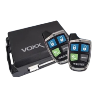
Related product manuals