EasyManua.ls Logo

Prestige APS622E User Manual

Prestige APS622E
16 pages
To Next Page IconTo Next Page
Page #1 background imageLoading...
Page #1 background image
128-9351
1 of 16
Page 1
Model APS622E
Installation Manual
PATENTED: www.voxxintl.com/company/patents
Table Of Contents:
Before You Begin Page 2
Wire Harness Quick View Page 3
Installation Of The Major Components Page 4
6 Pin Power Harness Page 5
Door Lock / Unlock Harness Page 6 & 7
12 Pin Input/Output Harness Page 7 - 9
4 Pin Main Harness Page 9
Tachometer Programming Information Page 9 & 12
Transmitter Programming Information Page 10
Feature Bank 2 Program Information Page 10 & 11
Feature Bank 3 Program Information Page 12 & 13
Diagnostics Page 14
Data Bus Port Information Page 14
Completing The Installation Page 14
Circuit Wiring Diagram Page 16
FCC NOTICE
This device complies with part 15 of the FCC rules. Operation of this device is subject to the following
conditions:
(1) This device may not cause harmful interference, and
(2) This device must accept any interference received, including interference that may cause undesired
operation.
Caution: Changes or modications not expressly approved by the party responsible for compliance voids
the users authority to operate this device.
Question and Answer IconNeed help?

Do you have a question about the Prestige APS622E and is the answer not in the manual?

Prestige APS622E Specifications

General IconGeneral
BrandPrestige
ModelAPS622E
CategoryRemote Starter
LanguageEnglish

Summary

Before You Begin Installation

Major Component Installation Guide

Control Module Mounting

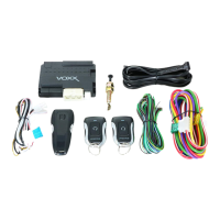
Instructions for selecting a mounting location for the control module inside the vehicle.

Antenna and Valet Switch Assembly

Guidance on routing and securing the receiver/antenna and valet switch assembly.

Hood Pin Switch Installation

Proper installation of the hood pin switch for safety shutdown functionality.

Vehicle Wiring Harness Connections

6-Pin Power Harness Wiring

Detailed wiring connections for the 6-pin power harness, including ignition and battery.

2-Pin Door Lock/Unlock Harness

Wiring instructions for the 2-pin harness controlling vehicle door locks and unlocks.

12-Pin Input/Output Harness Details

Additional Harnesses and Tach Programming

4-Pin Main Harness Wiring

Wiring instructions for the 4-pin main harness, including ground and parking lights.

Antenna Receiver Connector Setup

Connecting the 5-wire antenna receiver harness to the control module.

Tachometer Rate Programming

Procedure to program the tachometer signal for accurate engine speed monitoring.

System Programming Banks

Programming Bank 1: Transmitters

Steps to program remote transmitters for system control.

Programming Bank 2: Alarm Features

Configuration of alarm-related features and system settings.

Selectable Feature Options

Remote Start Bank 3 Programming

Engine Input Check Configuration

Example for setting the engine input check to DBI Tach mode.

RF Programmable Features (Bank 3)

Diagnostics and Installation Completion

Diagnostic Mode Codes

Interpreting parking light flash codes to diagnose last remote start shutdown.

4-Pin Data Bus Port (DBI)

Information on connecting the DBI port with compatible Audiovox interface modules.

Final Installation Steps

Procedures for completing the installation, including safety checks and customer explanation.

Related product manuals