128-9351
9 of 16
Page 9
12 Black/White Wire: (-) Horn Output
The black w/ white trace wire is provided to beep the vehicle’s horn. This is a transistor-
ized low current output, and should only be connected to the low current ground output
from the vehicle’s horn switch.
If the vehicle uses a + 12 VDC horn switch, then connect the black w/ white trace wire
to terminal 86 of a 30Amp automotive relay, and connect relay terminal 85 to a fused
+ 12 VDC battery source. Connect relay terminal 87 to the vehicle’s horn switch output,
and connect relay terminal 30 to a fused + 12 VDC battery source
NOTE: The outputs above are low current outputs and must be used with a relay if the
circuit’s requirement is more than 250 mA.
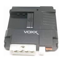
4 Pin Main Harness, Connector (P/N 1124320)
1) Black Wire: Chassis Ground
Connect the Black wire to a known vehicle ground source or to a solid clean metal part
of the chassis. Be certain to remove any paint or grease and secure this wire with a
self tapping screw and ring terminal.
2) White w/ Red trace Wire: Parking Light Relay Input Wire
This wire is the common contact of the on board parking light asher relay. If the vehicle
you are working on has +12 volt switched parking lights, connect this wire to a fused +
12 volt source. (Max. 15 Amps)
NOTE: If the vehicle’s parking lights are ground switched, connect this wire to chassis
ground.
3) Yellow w/ Black trace Wire: (+) Output To Alarm Ignition Input
This is the positive output that will connect to an alarm system allowing the alarm to
operate while under control of the remote start. This wire can connect to an existing
alarm system, or if available to the factory alarms ignition input.
4 White Wire: Parking Light Relay Output
This wire is the normally open contact of the on board parking light ash relay. Connect
this wire to the vehicle’s parking light feed wire. This is the wire that gets switched on,
either (+) or (-), when the vehicle’s parking light switch is activated.
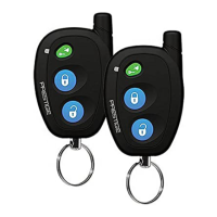
5 Wire Antenna Receiver Connector (P/N 1124318)
Connect the mating end of the previously mounted receiver harness to the mating
connector on the module. This harness will be the supply for the LED, Valet Switch as
well as the RX & 5VDC of the receiver.
Programming Tach Rate:
NOTE: All applications require that tach be programmed.
The unit will not operate unless tach is programmed. If an attempt is made to
start the vehicle via the remote start without rst programming tach, the unit
will ash the parking lights 7 times indicating tach has not been learned and
stored. If the tach rate is not properly programmed for the specic vehicle, the
unit may not realize that the vehicle is running and in certain instances re-en-
gage the starter motor.
The Remote Start Unit will learn the tach rate of most vehicle’s single coil, multiple coil
packs, or single injector.