128-9351
14 of 16
Page 14
Diagnostics:
Enter Bank 3 and turn on selectable feature # 9 as described in the feature selection
and setting section.
Exit the feature selection mode then press and hold the pushbutton valet/program switch
and then turn the ignition switch to the on position.
NOTE: Diagnostic mode is a temporary mode. Once you have accessed the diagnostic
mode, the unit will pause for two seconds then begin to ash the last stored
shut down code. This code will be displayed three times in succession, then
the unit will automatically exit the diagnostic mode.
The parking lights will ash a number of times indicating the reason for the last remote
start shutdown. The light ash indications are as follows:
1 Flash Run timer expired
2 Flashes Low or no tach signal (RPM)
3 Flashes Positive inhibit wire activation
5 Flashes RF shutdown signal received, or manual start trigger wire reactivated.
6 Flashes High tach signal (RPM)
7 Flashes Tach signal has not been learned
8 Flashes Negative inhibit wire activation
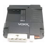
4 PIN DATA BUS PORT (DBI Port)
The 4 pin port located on the side of this module is for proprietary Audiovox data bus
interface modules. These modules are used to access a variety of features in the vehicle
which can be as simple as door trigger inputs, to more complex door lock outputs, or
transponder interfaces for remote starting. DO NOT connect anything to this port other
than the Audiovox DBI interface modules or damage to the Remote Start will occur. All
installation instructions for the DBI modules will be packaged with the individual com-
ponent along with the proper 4 pin wiring harness requires to access the data transmit
& receive as well as the proper voltage levels for the interface.
COMPLETING THE INSTALLATION:
After you have conrmed the operation of the Remote Start unit and tested all the safety
features of the system:
1. Mount the control module up and behind the dash securing it in place with cable
ties or screws. Be certain that the chosen mounting location will not inhibit any of
the controls of the vehicle.
2. Securely harness and tie all wiring up and away from all hot and moving parts that they
may come in contact with under the dash board or in the engine compartment areas.
CAUTION: Particularly avoid the area around the steering shaft and column, as wires
can wrap around these mechanisms and impair the safe operation of the
vehicle.
3. Apply the Caution Labels supplied with this kit to a conspicuous area in the engine
compartment. Make sure to clean the surface before afxing the label.
4. Check the vehicle’s wipers, lights, horn, etc, to insure proper operation.
5. Replace all panels that were removed during installation, and retest the system.
6. Explain all activated features and safety systems associated with Remote Start Unit
installed to the customer.