EasyManua.ls Logo

Prestige APS 685 - User Manual

Default Icon
20 pages
Print Icon
To Next Page IconTo Next Page
Loading...
128-5861A
1 of 20
Model APS 685
Installation Manual
4 Channel Remote Start / Keyless Entry System
Installation Instructions
This Unit Is Intended For Installation In Vehicles With
12 Volt Negative Ground Electrical Systems,
Gasoline or Diesel With True Tach Reference
And Automatic Transmissions Only.
Kit Contents
APS-685 Control Module
(2) - 4 Button Anti Code Grabbing Transmitters
4 Channel Code Learning Receiver
External Superheterodyne Antenna/Receiver
(1) - Multi Pin Input/Output Harness
(1) - Six Pin Power Harness
(1) - Four Pin Auxiliary Harness
(1) - Two Pin I/O Harness
(1) - Accessory 2 Pin Connector
(1) - 2 Pin Door Lock Harness
(2) - 30 Amp In-line Fuse Holders With Fuses
(1) - Control Switch
(1) - Programming Switch
(1) - Ring Terminal
(4) - 1/2" Long Screws
(1) - Pin Switch
(1) - Remote Start Warning Label
(1) - Literature Package
Released 9-7-00.
Revision A: F8 Default=On, 1 Flash= Off, 2 Flash= On page 13. 12-19-00.

Other manuals for Prestige APS 685

Question and Answer IconNeed help?

Do you have a question about the Prestige APS 685 and is the answer not in the manual?

Summary

Major Component Installation

Control Module Mounting

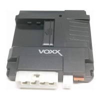
Select and secure the control module inside the vehicle's passenger compartment.

Hood Pin Switch Installation

Install the hood pin switch for safety shutdown of the remote start unit.

Receiver;Antenna Assembly Placement

Mount the receiver/antenna assembly for optimal RF reception above the belt line.

Programming & Control Switch Installation

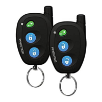
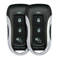
Install program and control switches in accessible locations for system operation.

Comprehensive Wiring Guide

6-Pin Main Power Harness Wiring

Connect the 6-pin harness wires for power, ignition, and starter circuits.

12-Pin Input;Output Harness Wiring

Connect the 12-pin harness for chassis ground, inhibit inputs, and outputs.

Specific Wire Functions and Harnesses

Details on light blue, green/orange, and door lock harness wire functions.

Auxiliary and Accessory Output Wiring

Wiring for 4-pin auxiliary and 2-pin accessory output harnesses.

Input;Output Harness Connections

Connect external trigger and entry illumination wires for specific functions.

Programming and Diagnostics

RF Programmable Features Setup

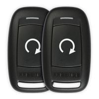
Configure system features like door locks, run time, and lights via RF transmitter.

Tach Rate Programming

Learn and program the vehicle's tach rate for proper remote start operation.

System Diagnostics and Troubleshooting

Use diagnostics to identify shutdown reasons from the last remote start attempt.

Operation, Testing, and Safety Procedures

Timed Start Program and Operation

Set up and operate the timed start feature for automatic vehicle starting.

Installation Testing Procedures

Perform critical tests for hood pin, manual shut down, and neutral start safety.

Neutral Safety Switch Considerations

Understand mechanical safety switch differences and ECM input connections.

Key In Sensor Circuit Methods

Implement methods 1 and 2 for key-in sensor circuits to ensure safety.

Final Installation Steps

Complete the installation, secure wiring, and apply labels before customer delivery.

Overall Wiring Diagram

APS-685 System Wiring Diagram

A comprehensive diagram illustrating all connections for the APS-685 unit.

Prestige APS 685 Specifications

General IconGeneral
Engine StartYes
Engine KillYes
Trunk ReleaseYes
Door Lock/UnlockYes
AlarmYes
Valet ModeYes

Related product manuals