EasyManua.ls Logo

Prestige APSRS1Z - User Manual

Prestige APSRS1Z
16 pages
Print Icon
To Next Page IconTo Next Page
Loading...
128-9480
1 of 16
Page 1
Model APSRS1Z
Installation Manual
PATENTED: www.voxxintl.com/company/patents
Table Of Contents:
Before You Begin Page 2
Wire Harness Quick View Page2 & 3
Installation Of The Major Components Page 4
Wiring The 6 Pin Main Power Harness Page 5
3 Wire Negative Switched Door Lock Circuits Page 6 & 7
Wiring The 10 Pin Input/Output Harness Page 7 - 9
4 Pin Main Harness Page 9
5 Wire Antenna Receiver Connector Page 9
Tachometer Rate Programming Page 10 & 12
Programming Bank 1 (Transmitter) Page 10
Programming Bank 2 (Alarm Features) Page 10 & 11
Programming Bank 3 (Remote Start) Page 12 & 13
Diagnostics Page 14
4 Pin Data Bus Port Page 14
Completing The Installation Page 15
Circuit Wiring Diagram Page 16
FCC COMPLIANCE
This device complies with part 15 of the FCC Rules. Operation is subject to the following two conditions:
(1) This device may not cause harmful interference, and
(2) this device must accept any interference received, including interference that may cause undesired operation.
This equipment has been tested and found to comply with the limits for a Class B digital device, pursuant to part 15 of the FCC Rules. These
limits are designed to provide reasonable protection against harmful interference in a residential installation. This equipment generates, uses
and can radiate radio frequency energy and, if not installed and used in accordance with the instructions, may cause harmful interference to
radio communications. However, there is no guarantee that interference will not occur in a particular installation. If this equipment does cause
harmful interference to radio or television reception, which can be determined by turning the equipment off and on, the user is encouraged to
try to correct the interference by one or more of the following measures:
—Reorient or relocate the receiving antenna.
—Increase the separation between the equipment and receiver.
—Connect the equipment into an outlet on a circuit different from that to which the receiver is connected.
—Consult the dealer or an experienced radio/TV technician for help.
Warning!
Changes or modications made to this equipment not expressly approved by the part responsible for compliance could void the use’s author-
ity to operate the equipment
NOTE: The manufacturer is not responsible for any radio or TV interference caused by unauthorized modications to this
equipment. Such modications could void the user’s authority to operate the equipment.
Question and Answer IconNeed help?

Do you have a question about the Prestige APSRS1Z and is the answer not in the manual?

Summary

Before You Begin

Installation of Major Components

Control Module

Details on selecting a mounting location for the control module and avoiding interference.

Receiver;Antenna Valet Switch LED Assembly

Instructions for mounting the receiver/antenna assembly for optimal reception, considering window types.

Hood Pin Switch

Guidance on mounting the hood pin switch for safety shut down, ensuring proper activation.

Wiring the 6 Pin Main Power Harness

3 Wire Negative Switched Door Lock Circuits

Wiring the 10 Pin Input;Output Harness

4 Pin Main Harness

5 Wire Antenna Receiver Connector

Programming Tach Rate

Programming Bank 1 (Transmitters)

Programming Bank 2 (Alarm Features)

Selectable Features

Programming Bank 3 (Remote Start)

RF Programmable Features Bank 3

Diagnostics

4 Pin Data Bus Port (DBI Port)

Details about the 4-pin data bus port for proprietary Flash-Logic data bus interface modules.

Completing the Installation

Overview

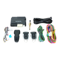
This document is the installation manual for the Prestige Model APSRS1Z Remote Start System, designed for automatic transmission, fuel injection vehicles. It provides comprehensive instructions for installing, wiring, programming, and troubleshooting the device.

Function Description

The Prestige APSRS1Z is a remote start system that allows users to remotely start their vehicle. It includes features for vehicle security, such as door lock/unlock control, and integrates with the vehicle's existing systems like the ignition, accessory, starter, and parking lights. The system also incorporates safety features, including a hood pin switch to prevent remote start activation when the hood is open, and diagnostic capabilities to identify issues.

Important Technical Specifications

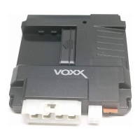
Control Module (P/N 1365589):

  • Mounting location: Inside the passenger compartment, up behind the dashboard, within 24" of the ignition switch wiring harness.
  • Not waterproof; must not be mounted in the engine compartment.

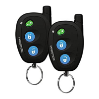
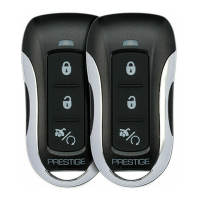
Receiver/Antenna Valet Switch LED Assembly (P/N 1181256):

  • Superheterodyne Receiver Antenna for maximum operating range.
  • Includes LED and Valet/Programming switch.
  • Mounting location: Above the belt line (dashboard) for best reception. Special consideration for metallic shielded window glass; may require routing antenna toward a rear window.
  • Connects via a 5-pin cable to the control module.

Hood Pin Switch (P/N 1363699):

  • Function: Supplies a ground to inhibit remote start when the hood/trunk is open. Required for safety shutdown.
  • Mounting: To a grounded metal surface, away from water drain paths. Must be depressed at least 1/4 inch when the hood is closed.
  • Drilling: Requires a 1/4" hole for direct mounting, or a pre-threaded bracket hole.

Wiring Harnesses:

6 Pin Power Harness (P/N 1124317):

  • 1 Blue Wire: Ignition 1 Output (+12V when key is ON/RUN/START, 0V when OFF/ACCESSORY).
  • 2 Red/White Trace Wire: Battery 1 - 12V (+) Source (20A Max). Provides power for control circuit, Ignition 1 and Ignition 2 relays.
  • 3 Green Wire: Ignition 2 Output (+12V when key is ON/RUN/START, 0V when OFF/ACCESSORY). Can be programmed to output during START mode (Bank 3 Selection #7).
  • 4 Purple Wire: Accessory Output (+12V when key is ACCESSORY/ON/RUN, 0V when OFF/START/CRANK).
  • 5 Red Wire: Battery 2 - 12V (+) Source (30A Max). Provides power for start and accessory relays.
  • 6 Yellow Wire: Starter Output. Connects to low current start solenoid wire. Critical for safety to prevent in-gear starting; requires testing to ensure vehicle cannot start in any gear other than park or neutral.
  • Fuses must be used and located close to the power source for protection.

10 Pin Input/Output Harness (P/N 1124316):

  • 1 Green/Orange Wire: Tachometer Input Signal. Monitors engine tach rate. Connects to vehicle ECM tach input or negative side of ignition coil.
  • 2 Empty Cavity: NA (No Connection).
  • 3 Black/Blue Wire: Pulsed Negative Output Before Start (1 second, 250mA). Activates 1 second before remote start and when transmitter unlocks system. Used to disarm factory theft deterrent systems.
  • 4 Black/LT. Green Wire: Pulsed Ground Output After Start (1 second, 250mA). Activates after vehicle starts. Used to re-lock doors if they unlock automatically when factory anti-theft disarms.
  • 5 LT. Blue Wire: Ground Output While Running Under Remote Start Control (250mA). Active 2 seconds before module initializes, remains grounded while active, plus 1 second after system turns off. Requires a relay for use in Shock Sensor Bypass, Additional Ignition Output, or GM VATS Key Override.
  • 6 Green/Yellow Wire: Diesel Wait To Start Input. Delays starter output until glow plug preheat circuit drops 12V. Overrides Bank 3 feature #11 if used.
  • 7 Brown Wire: Brake Positive Inhibit Input (+12V instant shutdown). Connects to output side of brake switch.
  • 8 Gray Wire: Negative Inhibit Input (Ground instant shutdown). Connects to hood pin switch. Must be tested for proper operation.
  • 9 Black/Red Wire: Pulsed Ground Output After Shutdown (1 second, 250mA). Activates after remote start unit shuts down. Used to re-lock doors if they unlock automatically when ignition transitions to off.
  • 10 Black/Yellow Wire: Ground Output During Start (Crank) (250mA). Activates while starter output is active. Used to activate Crank Low/Bulb Test Wire in GM vehicles or ECM wake up wire in Chrysler vehicles.
  • NOTE: Outputs above 250mA require a relay.

4 Pin Main Harness (P/N 1124320):

  • 1 Black Wire: Chassis Ground. Connects to a known vehicle ground source.
  • 2 White w/ Red Wire: Parking Light Relay Input Wire. Common contact of on-board parking light flasher relay. Connects to fused +12V source (Max. 15 Amps) for +12V switched parking lights, or chassis ground for ground switched parking lights.
  • 3 Yellow w/ Black Wire: (+) Output To Alarm Ignition Input. Connects to an alarm system's ignition input to allow alarm operation during remote start.
  • 4 White Wire: Parking Light Relay Output. Normally open contact of on-board parking light flash relay. Connects to vehicle's parking light feed wire.

5 Wire Antenna Receiver Connector (P/N 1124318):

  • Connects the receiver harness to the module. Supplies LED, Valet Switch, RX, and 5VDC to the receiver.

4 Pin Data Bus Port (DBI Port):

  • Proprietary port for Flash-Logic data bus interface modules. Used for door trigger inputs, door lock outputs, or transponder interfaces.
  • DO NOT connect anything other than appropriate Data Bus Interface modules to this port.

Usage Features

Installation Guidelines:

  • Professional Installation: Strongly recommended.
  • Safety First: Roll down windows to avoid locking keys inside. Avoid routing wires near hot surfaces or moving parts. Use grommets for wires through metal.
  • Testing: Use a Digital Multi Meter for testing; avoid "TEST LIGHT" or "COMPUTER SAFE PROBE" to prevent damage to vehicle electronics.
  • Pre-connection: Do not plug in main power or input/output harnesses until all vehicle connections are made. Disconnect negative battery cable before making connections.

Programming:

  • Tach Rate Programming (Required for all applications):
    1. Turn ignition key to ON.
    2. Press and release valet/program switch 3 times.
    3. Turn ignition key OFF.
    4. Press and hold valet/program switch, then start vehicle with key.
    5. Parking lights flash when tach signal is sensed (wait for at least 5 flashes).
    6. Release switch. Parking lights illuminate for 3 seconds, indicating tach signal is stored.
    7. If tach learn fails (parking lights do not flash), correct tachometer connection (Green/Orange Wire) and repeat.
  • Programming Bank 1 (Transmitters):
    1. Turn ignition key to ON.
    2. Press and release valet/programming switch 3 times (lights flash once).
    3. Press button on each transmitter to be programmed until parking lights flash.
    4. Turn ignition switch OFF to exit.
  • Programming Bank 2 (Alarm Features):
    1. Enter from Bank 1 by turning ignition key OFF then ON (lights flash twice), or directly:
    2. Turn ignition key to ON.
    3. Press and release valet/programming switch 3 times (lights flash once).
    4. Turn ignition key OFF then ON (lights long flash).
    5. Press pushbutton switch to advance to desired feature (once for feature 1, twice for feature 2, etc.).
    6. Use transmitter button to select feature setting.
    7. Turn ignition key OFF to exit (parking lights flash upon exit).
  • Programming Bank 3 (Remote Start):
    1. Enter from Bank 2 by turning ignition key OFF then ON (Pk. Lts flash twice), or directly:
    2. Turn ignition key to ON.
    3. Press and release valet/programming switch 3 times (lights flash once).
    4. Turn ignition key OFF then ON (lights long flash).
    5. Turn ignition key OFF then ON (lights two long flashes).
    6. Press pushbutton switch to advance to desired feature.
    7. Use transmitter button to select feature setting.
    8. Turn ignition key OFF to exit. Programming mode automatically exits if no activity on pushbutton switch or transmitter lock button.

Selectable Features (Banks 2 & 3):

  • Detailed tables for selectable features in Bank 2 (Alarm Features) and Bank 3 (Remote Start Selectable Features) are provided, including default settings (BOLD text).
  • Features include door lock/unlock timing, accessory lock/unlock, headlights, passive locks/arming, siren/horn options, trigger circuits, input checks (Voltage, Tach, DBI Tach, Hybrid), run time, crank time, gas/diesel settings, transponder output, temp start, crank averaging, R/S shock, turbo select, and auxiliary outputs.

Diagnostics:

  • Automatic diagnostic mode indicated by parking light flashes after a failed start or premature shutdown.
  • Flash Codes:
    • 1 Flash: Run timer expired
    • 2 Flashes: Low or no tach signal (RPM)
    • 3 Flashes: Positive inhibit wire activation
    • 4 Flashes: Manual Transmission Mode Error
    • 5 Flashes: RF shutdown signal received, or manual start trigger wire reactivated.
    • 6 Flashes: High tach signal (RPM)
    • 7 Flashes: Tach signal has not been learned
    • 8 Flashes: Negative inhibit wire activation

Maintenance Features

Completing the Installation:

  1. Mount Control Module: Securely mount up and behind the dash with cable ties or screws, ensuring it doesn't inhibit vehicle controls.
  2. Secure Wiring: Harness and tie all wiring away from hot and moving parts, especially around the steering shaft/column.
  3. Apply Caution Labels: Affix supplied labels in a conspicuous area in the engine compartment after cleaning the surface.
  4. Check Vehicle Functions: Verify proper operation of wipers, lights, horn, etc.
  5. Replace Panels: Reinstall all removed panels and retest the system.
  6. Customer Explanation: Explain all activated features and safety systems to the customer.

Technical Support:

  • Website: www.avxtech1.com or www.prestigecarsecurity.com
  • Phone: 1 800 225 6074

Prestige APSRS1Z Specifications

General IconGeneral
BrandPrestige
ModelAPSRS1Z
CategoryRemote Starter
LanguageEnglish

Related product manuals