9-6 TECHNICAL INFORMATION
PA1633 X3-45 Commuter Operator’s Manual
ANTILOCK BRAKING SYSTEM (ABS)
The antilock braking system has one Electronic
Control Unit (ECU) controlling a four channel
system. A wheel slip sensor is mounted at each
front axle and drive axle wheel. The Tag axle
wheels are slave to the drive axle wheels.
The Electronic Control Unit (ECU) is
maintenance free. Its operating voltage is 24 ±
6 volts DC. The thermal operating range for the
ECU is from -40 to 167°F (-40 to 75°C).
The solenoid control valves are maintenance
free. Their operating voltage is 24 (+4.8, -2.4)
volts DC. The rated current draw is 1.65 amps.
The thermal operating range of the solenoid
control valves is from -40 to 176°F (-40 to 80°C).
STEERING
• ZF 8098 integral hydraulic assisted steering
gear;
• Volvo hydraulic pump gear driven from
engine drive.
• Hydraulic reservoir and dipstick accessible
from engine compartment.
• System pressure: 2320 psi (160 bars).
• Steering wheel diameter 18". Tilt steering
wheel and telescopic steering column;
pneumatically locked with foot operated
switch for adjustment.
• Number of turns: 5¾.
• Outside turning radius: See Dimensions and
Weight.
ELECTRICAL SYSTEM
• 24-volt, negative ground;
• 12-volt exterior lighting;
• Three 28 volts, 150 amp, self-regulated,
belt-driven, air-cooled HD 10 Bosch
alternators;
• Four 12 volt, Group 31 AGM batteries
connected in series/parallel. Cold cranking
capacity is 800 amps @ 0
o
F (-18
o
C) (each
battery) with a reserve capacity of 200
minutes;
• 100 amp battery equalizer.
SUSPENSION
Goodyear rolling lobe type air springs (bellows)
are used throughout.
I-BEAM AXLE FRONT SUSPENSION
2 Bellows (12
"); for a G.A.W.R. of 16,500 lb;
2 Shock absorbers;
4 Radius rods;
1 Transverse radius rod;
1 Height control valve.
1 sway bar (1¾
" diameter).
DRIVE AXLE
4 Bellows (11
");
4 Shock absorbers;
3 Radius rods;
1 Panhard rod;
2 Height control valves.
TAG AXLE
2 Bellows (11
");
2 Shock absorbers;
3 Radius rods;
1 Panhard rod.
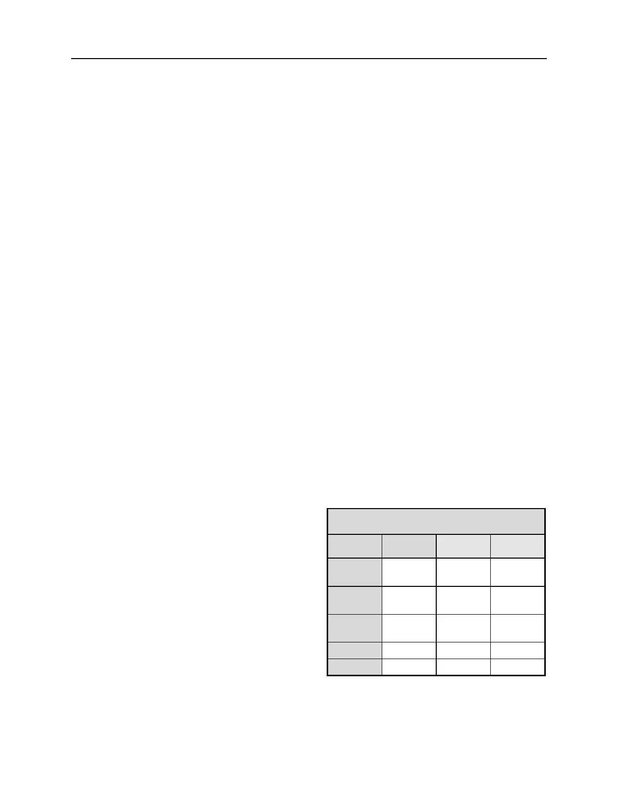
ALIGNMENT SPECIFICATIONS
Use static wheel alignment systems which work
with angle measurements only, such as Josam or
Hunter systems. Static alignment specifications
are listed in the following tables:
I-BEAM AXLE FRONT SUSPENSION
Right
camber
-0.250° 0.125° 0.375°
Left
camber
-0.250° 0.125° 0.375°
Right
caster
2.0° 2.75° 3.5°
Left caster
2.0° 2.75° 3.5°
Total toe
0.04° 0.06° 0.08°
 Loading...


